Learn More About How A Monostable Works
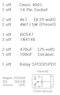
Construction GuideClick here if you're new to constructing stripboard projects.The prototype of the timer was built using only the Stripboard Layout as a guide. So - if you reproduce the layout - you will have a working timer. Details of how to Test Your Finished Circuit Board are also provided. The terminals are a good set of reference points. To fit them - you may need to enlarge the holes slightly. Then turn the board over and use a felt-tip pen to mark the 16 places where the tracks are to be cut. Before you cut the tracks - use the "actual size" drawing to Check That The Pattern is Correctly Marked . 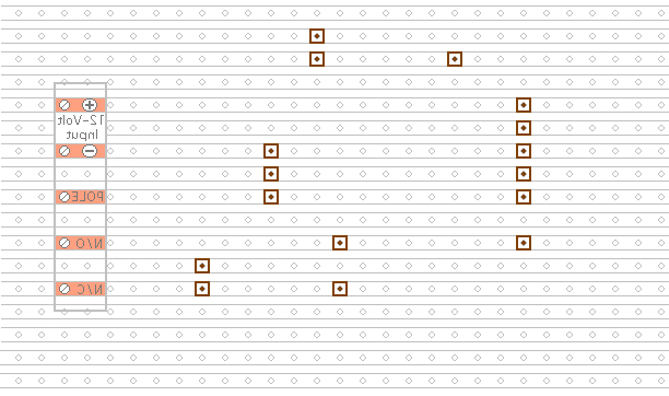
Actual Size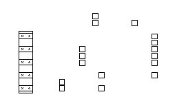
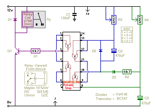
Next make and fit the Nine Wire Links - fit the two presets - and fit the two fixed resistors. For the links - I used bare copper wire on the component side of the board. Telephone cable is suitable - the single stranded variety used indoors to wire telephone sockets. Stretching the core slightly will straighten it - and also allow the insulation to slip off. 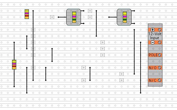
Then fit the three diodes and the transistor. Pay particular attention to the orientation of the diodes. See the Photograph Of The Prototype. Note that D3 is facing downwards. 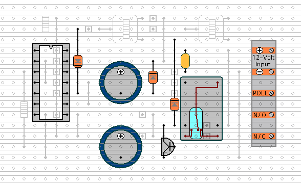
Next, fit the three capacitors - the relay - and the IC socket. Pay particular attention to the orientation of the electrolytic capacitors. Note that each has its negative terminal - the side with the stripe - facing downwards. Turn the board over and examine the underside carefully - to make sure that there are no unwanted solder bridges or other connections between the tracks. If you backlight the board during the examination - it makes potential problem areas easier to spot. When you're satisfied that everything is in order - add the 7 solder bridges. These are just small blobs of solder. They connect two adjacent tracks together. They're like very short wire links. 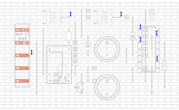
Finish off by inserting the Cmos IC into the socket. Pin 1 of the IC should be in the top left-hand corner. Check that all 14 pins have entered the socket. Sometimes - instead of entering the socket - a pin will curl up under the IC. General Information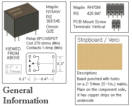
Click Here For A Photograph Of The Prototype.
| ||||||||||||||||||||||||||||
 SUGGESTIONS