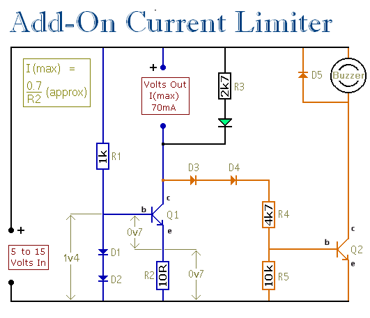
Build this simple circuit yourself using veroboard or stripboard - and a handful of cheap off-the-shelf components. Connect it to the output terminals of your power supply - and it will protect both your PSU - and the device you're powering-up.
Parts List
|
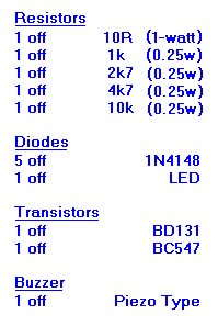
|
|
|
Construction Notes
Click here if you're new to constructing stripboard projects
The terminals are a good set of reference points. To fit them, you may need to enlarge the holes slightly. Then turn the board over and use a felt-tip pen to mark the 4 places where the tracks are to be cut. Before you cut the tracks - double check that your marks are in the right place.
When you're satisfied that the pattern is right - cut the tracks. Make sure that the copper is cut all the way through. Sometimes a small strand of copper remains at the side of the cut and this will cause malfunction. Use a magnifying glass - and backlight the board. It only takes the smallest strand of copper to cause a problem. If you don't have the proper track-cutting tool, then a 6 to 8mm drill-bit will do. Just use the drill-bit as a hand tool - there's no need for a drilling machine.
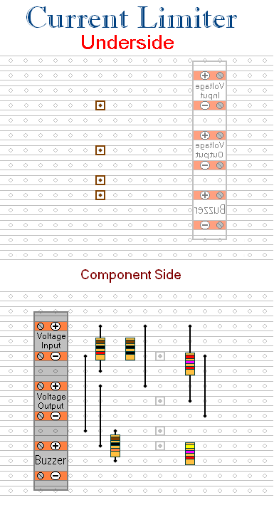
Start by making and fitting the Four Wire Links. I used bare copper wire on the component side of the board. Telephone cable is suitable - the single stranded variety used indoors to wire telephone sockets. Stretching the core slightly will straighten it - and also allow the insulation to slip off.
Next - fit the 5 resistors. The resistors are all shown lying flat on the board. But those connected between close or adjacent tracks are actually mounted standing upright.
Then fit the five diodes - the BC547 - and the LED. Pay particular attention to the orientation of the diodes. Note that D5 - across the Buzzer terminals - faces in the opposite direction to the other diodes. Again, the diodes are all shown lying flat on the board - but those connected between adjacent tracks are actually mounted standing upright.
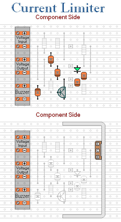
Finally, fit the BD131 and the heatsink. If you have set a high maximum current limit - and the output may be overloaded for long periods of time - you should increase the size of the heatsink. The transistor has to dissipate most energy when the output terminals are shorted together. Try it. If the BD131 is getting too hot to touch - your heatsink is inadequate.