Build this DIY Burglar Alarm System using cheap off-the-shelf components. It has automatic Exit and Entry delays and a timed bell Cut-off. Use it in your home - small business premises - lock-up - caravan - mobile home, camper van etc.
Learn More About The Cmos 4011
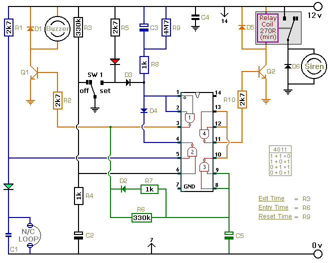
Power Supply
The circuit itself should not use more than a few milliamps. It is only when the relay is energised and the siren is sounding that any real current is required. The actual current consumption depends on the sounder you use. A conventional bell uses up to about 400ma. An electronic siren generally uses less. In any case, a 1-amp power supply should be sufficient. The Alarm Power Supply is ideal.
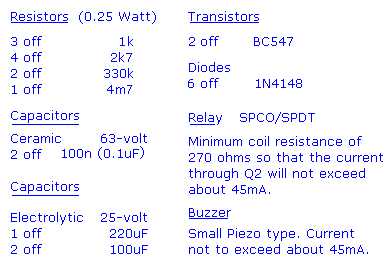
Parts List
|
|
|
Construction
Click here if you're new to constructing stripboard projects.
The terminals are a good set of reference points. To fit them - you may need to enlarge the holes slightly. Then turn the board over and use a felt-tip pen to mark the 26 places where the tracks are to be cut. Before you cut the tracks, use the "actual size" drawing to Check That The Pattern is Correctly Marked .
When you're satisfied that the pattern is right - cut the tracks. Make sure that the copper is cut all the way through. Sometimes a small strand of copper remains at the side of the cut and this will cause malfunction. Use a magnifying glass - and backlight the board. It only takes the smallest strand of copper to cause a problem. If you don't have the proper track-cutting tool - then a 6 to 8mm drill-bit will do. Just use the drill-bit as a hand tool - there's no need for a drilling machine.
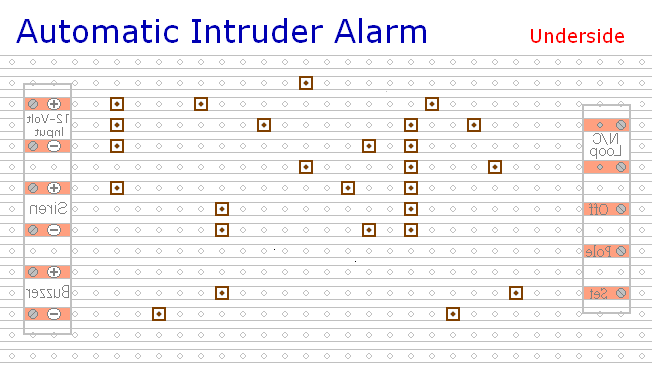
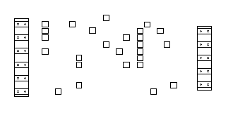
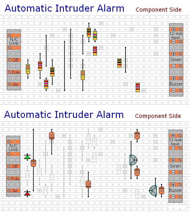
Actual Size Of Pattern
Next fit the 10 resistors and the Five Wire Links. For the links - I used bare copper wire on the component side of the board. Telephone cable is suitable - the single stranded variety used indoors to wire telephone sockets. Stretching the core slightly will straighten it - and also allow the insulation to slip off.
The resistors are all shown lying flat on the board. However, those connected between close or adjacent tracks are mounted standing upright. See The Photograph Of The Prototype
The next stage is to fit the diodes and transistors. You'll want to mount the LEDs where they can be seen - perhaps on the front of your alarm-panel. They should be connected to the circuit board using a light flexible wire - e.g. the cores from a piece of alarm cable. They may be attached to the circuit board from the front or the rear. Make them long to begin with. You can shorten them later when you assemble your alarm-panel. Twist the wires into pairs to keep them tidy
Fit the remaining seven components (capacitors, relay and IC socket). Using a socket reduces the chances of damaging the IC - and makes it easier to replace if necessary.
Pay particular attention to the orientation of the electrolytic capacitors. Note that electrolytic capacitors generally have a light coloured stripe down the side next to the negative terminal. C2 is mounted with its positive terminal facing downwards. See The Photo Of The Prototype
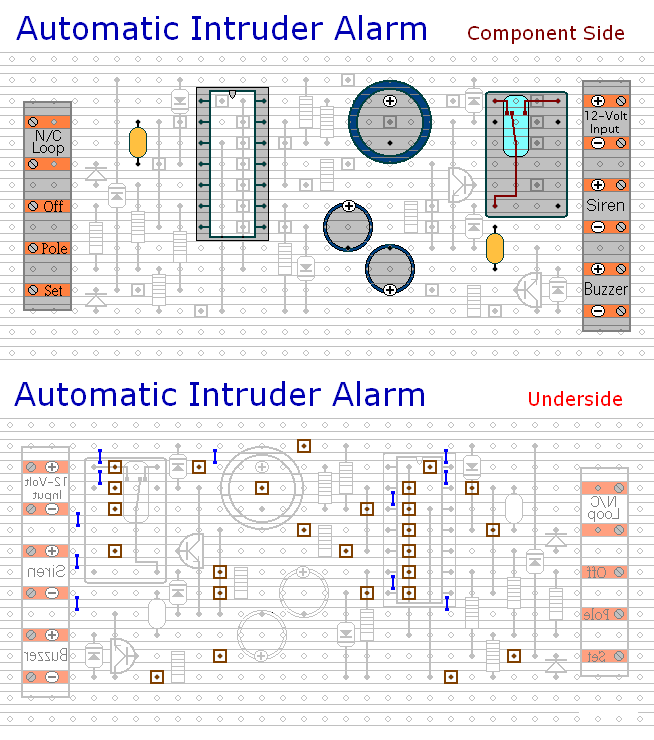
Examine the underside of the board carefully - to make sure that there are no unwanted solder bridges or other connections between the tracks. If you backlight the board during the examination - it makes potential problem areas easier to spot. When you're satisfied that everything is in order - add the 11 solder bridges.
Finish off by inserting the Cmos 4011 into the socket. Pin 1 of the IC should be in the top left-hand corner. Check that all 14 pins have entered the socket. Sometimes - instead of entering the socket - a pin will curl up under the IC.
You're Now Ready To Test Your Circuit
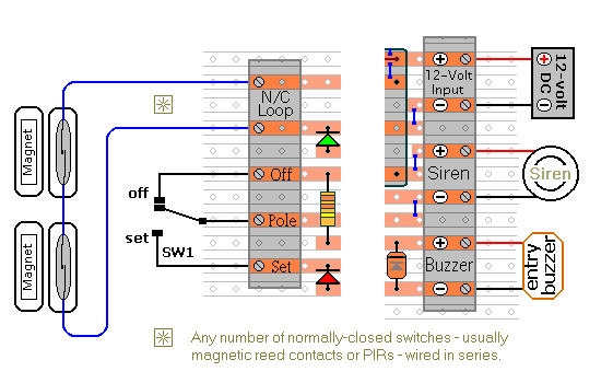
Connections
Modification No.1
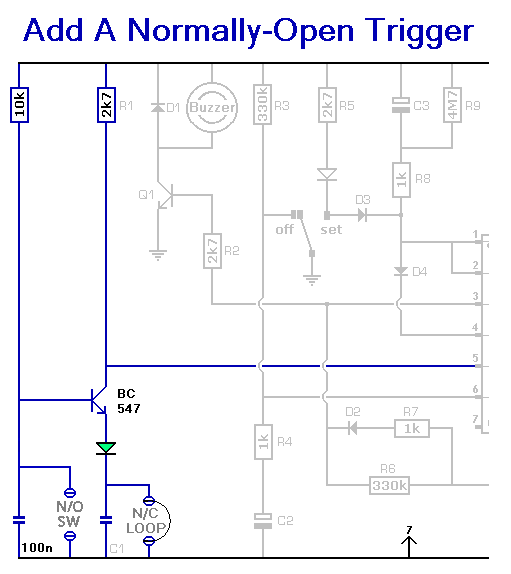
Modification No.2
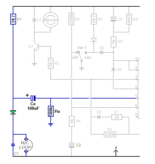
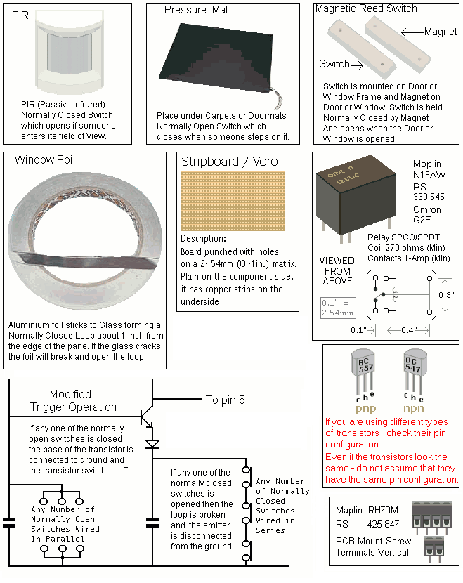
The following simple modification to the trigger circuit - will cause the Siren cut-off timer to run - the moment the alarm is activated. In other words - the Siren will stop after 15-minutes - regardless of the state of the loop.
General Information
Test Your Finished Circuit Board
 SUGGESTIONS