Three circuits that combine a regular doorbell with a flashing LED display. Multiple LED displays are possible. So you can put one in every room. The doorbells cater for both the hearing and non-hearing members of the household.
Doorbell Circuit No.1
When the push switch is operated - the buzzer will sound and the LEDs will begin to flash. For the hearing members of the household - the buzzer acts as a regular doorbell. It also reassures the visitor that the doorbell is working.
When the push switch is released the buzzer will stop - but the LEDs will continue to flash. The length of time they will go on flashing is set by the values of R2 & C1. With the values shown in the diagram - the LEDs will flash for a further 30 seconds or so. Make R2 a variable resistor - and you can adjust the time period more precisely. If 30 seconds is not long enough - increase the value of C1.
Groups of up to three LEDs may be connected to the output pins of gates 3 & 4. Each group must have its own series resistor. And the value of the resistor depends on the number of LEDs in series with it. You don't have to use the two outputs. You can choose to use just a single group of LEDs - connected to a single output pin. If you do use both outputs - you can make one large display. Or you can have two smaller displays - each in a different room.
The speed at which the LEDs flash is controlled by the values of R3 & C2. With the values given in the diagram - the LEDs will flash at about the rate shown. Replace R3 with a 1Meg variable resistor - and you can adjust the speed of the flash. However - if you make it too fast - the flash effect will be lost - and the LEDs will appear to be on all the time.
Doorbell Circuit No.2
The last circuit will flash up to two groups of 3 LEDs in tandem. This circuit will flash the two groups alternately. The alternate flashing creates the illusion of movement - and makes the display more eye-catching. Note that - although I've drawn the two groups of LEDs side by side - the individual LEDs can be mounted in any pattern you like
The speed at which the LEDs flash is controlled by the values of R3 & C2. With the values given in the diagram - the LEDs will flash at about the rate shown. If you replace R3 with a 1Meg variable resistor - you can adjust the speed of the flash. However - make it too fast and you'll lose the flash effect.
Doorbell Circuit No.3
The main difference between this circuit and the last one - is the addition of the two transistor switches. The switches will each flash up to 15 groups of 3 LEDs. And - because they are getting power directly from the battery - the LEDs will glow at their full brilliance.
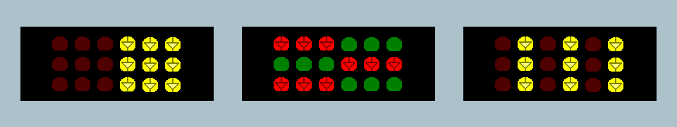
Alternate flashing creates the illusion of movement. In the diagram - the effect is not obvious. That's because the two groups are separate from one another. But mount them together - and the effect is clear. Any number of patterns are available. Here are just three possible examples.
TURN ON THE FLASH
These displays are made from just two groups of nine LEDs. But the BC337 has an Ic(max) of 500mA. So you can easily connect fifteen or more groups of LEDs to each transistor. This makes displays of 90 or more LEDs possible.
Learn More About The Cmos 4001
 SUGGESTIONS