COMMENTS
 SUGGESTIONS
|
Hijack Alarm No.3 - Testing Your Circuit |
MORE VEHICLE ALARMS |
|---|
|
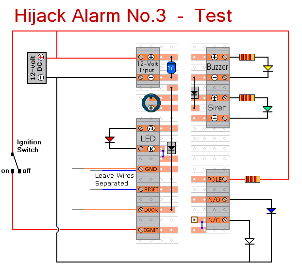
Schematic Diagram |
The Rest of Ron's Circuits | Write To Ron | More Free-to-Use Circuits | Circuit Exchange International |
|---|
Hijack Alarm No.3 - Construction Guide
Introduction
Once you're satisfied that your layout is correct - and you have made a careful and thorough check of the underside of the board - it's time to power-up the circuit and test its operation. This is always an anxious moment. If you construct a lot of circuits - you might consider building the Current Limiting Power Supply - or alternatively - you could add the Simple Current Limiter to your existing PSU. Both will let you set an upper limit on the amount of current supplied to your circuit - and so protect it from any serious damage.
Setup
|
Click Here For A Photograph Of The Prototype. |
|
|---|---|
|
|
If You Find a Problem
If you've built your circuit using the specified components - and you've followed the step-by-step construction guide provided - then the chances are that any bug will be caused by something minor - a component connected the wrong way round - a missing or unwanted solder bridge - an incomplete cut in the track etc. If you haven't used the specified transistors or SCR - check the pin configuration. Just because the components look the same - do not assume that they have the same pin configuration.
If you can't see anything obvious - adopt a systematic approach to faultfinding. Begin by double-checking that all of the cuts in the tracks have been made, that they are all - In The Right Place - and that they sever the track completely. Use a magnifying glass - and backlight the board. It only takes the smallest strand of copper to cause a problem.
When you're satisfied that the tracks have been severed in all the right places, check that you have made - and correctly placed - all twelve solder bridges. Mark each bridge with a felt-tip pen - or something similar - so that it can be easily identified later.
Next, carefully examine the full length of each track. Look for unwanted solder bridges. Your felt-tip markings will tell you which ones should be there - and help you identify any that shouldn't be there. Again, if you backlight the board during the examination - it makes potential problem areas easier to spot.
If all else fails and you still haven't found the cause of the problem - work your way through the assembly instructions provided. Check each individual component and link - to make sure that it's present and correctly positioned.
Print out the drawings and mark off the components as you go. Take your time and examine each individual component carefully. Pay particular attention to the orientation of the diodes, the transistors, the SCR and the electrolytic capacitors.
