This little circuit lets you measure both the switching voltage - and the hysteresis - of common Cmos inverters and non-inverters such as 4001, 4011, 4093, 4071, 4081.
Learn More About Cmos Inverters
A Cmos ICs will work at anything from 3v to 15v - some versions will even work with an 18v supply. A Cmos input pin is high when it's more than half of the supply voltage - and low when it's less than half of the supply voltage. Roughly speaking - with a 12v supply - anything over 7v is a high - and anything below 5v is a low. Somewhere between 5v and 7v is the crossover - or switching point of the gate. Depending on whether the voltage on the input pin is rising or falling - when it crosses this point - the output pin will switch from high to low - or vice-versa.
If you're designing timers - thermostats - light operated switches etc - the precise switching voltage of the Cmos gate may be important. For example - in the case of an RC timer - it will take the capacitor longer to charge to 7v - than it will to charge to 5v. So the actual time delay produced by any particular RC pair - will be acutely dependent on the switching voltage of the gate you're using. This page provides two small circuits that will allow you to measure the exact switching voltage of common Cmos inverters and non-inverters.
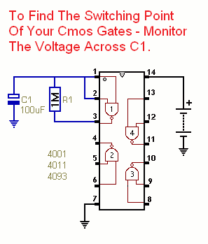
Circuit No.1 - Inverters
|
|
|
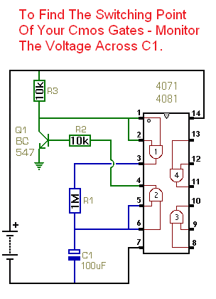
Circuit No.2 - Non-Inverters
|
|
|

 SUGGESTIONS