| This is a battery powered Infra-Red Link that will allow you to change channels on your Satellite Receiver and operate the controls on your VCR & DVD from anywhere in the house. |
|---|
This is a battery powered IR Link which may be used in more than one room. The standby current is extremely low - so battery life is excellent. And by shutting down in the presence of extraneous IR radiation - it copes with the problem of excessive output current.
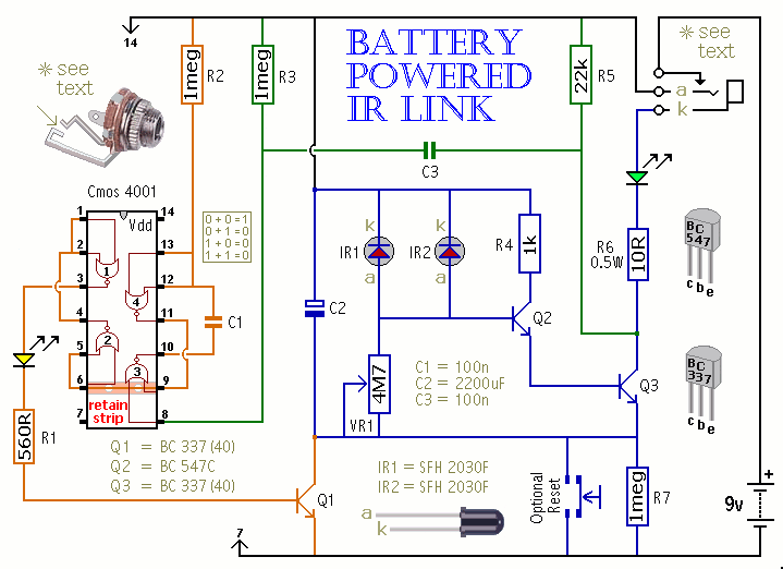
Schematic Diagram

Notes
This circuit is not powered directly from the battery. When a remote control signal is received - the energy stored in C2 - drives the emitter diode. At the same time - Q1 switches on briefly - and allows the battery to recharge C2. The green LED shows that the circuit is transmitting - and the yellow LED confirms that C2 has been topped-up.
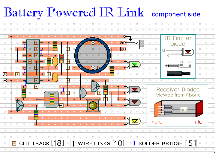
There is unwanted IR radiation in both daylight and tungsten lighting. To minimize its effect use an opaque housing and do not make the opening too large. (Try a horizontal slot measuring 2 cm X 1.5 cm.) Shade the receiver diodes by mounting them side-by-side a few centimetres deep - inside the case. The depth of shading required will depend on the lighting conditions. (Try 5 cm to start with).
To reduce the effects of visible light - use receiver diodes with a built-in daylight filter ( Maplin CY91Y). Or cover the opening using a small piece of dark transparent plastic. Part of the display panel from a scrap VCR is ideal. Position the unit out of direct light and avoid reflective surfaces. If all else fails, adjust VR1 to reduce sensitivity.
What you are aiming for is to ensure that in standby mode Q2 remains switched off so that C2 retains its charge. If unwanted radiation does reach the receiver it will not result in a large output current. C2 simply discharges and the circuit shuts down. When the source of the unwanted radiation is removed the unit may be reset by interrupting the power supply for a few seconds or by pushing the (optional) reset button. If you do neither then it will reset itself after about an hour when C2 has recharged through R7.
With two receiver diodes wired in parallel, the operating range is up to about 1 meter. The exact distance depends on the remote you are using and on the position of VR1 (start by setting it about halfway). Correctly focused - a plastic lens from a small magnifying glass will extend the distance.
I used the high gain version of the BC337 because that was what I had available. However, the only transistor whose gain is likely to be important is the BC547C. For the infrared emitter I used a TIL38 (Maplin YH70M) at the end of 12 meters of alarm cable. However, the diode from a scrap remote control should be worth trying also. Two diodes wired in series will give improved output performance.
The circuit was designed with a small 9-volt alkaline battery in mind (PP3, MN1604, 6LR61) but the prototype worked well at 6-volts using four AA batteries. The standby current was too small to measure reliably. An earphone socket makes the unit portable; so it can be used in more than one room.
If you can obtain the style of socket in the diagram - (Maplin HF82D) - its normally closed switch can be converted to a normally open switch by releasing the inner contact as shown. This means that it will act as an on/off switch when you unplug the lead. And - because it allows you to interrupt the power supply - there's no need for a reset button.
Veroboard Layout

 SUGGESTIONS
 SUGGESTIONS

