| All the information you need to build a simple keypad operated switch with a time lock - using cheap off-the-shelf components. |
|---|
Detailed Circuit Description
This circuit is designed to be used with the Universal Keypad Operated Switch. A few genuine mistakes - made during code entry - will not activate the device. But repeated attempts to find the correct code by trial and error - will cause the keypad to lock-up - and the Buzzer to sound. Connect the coil of a suitable relay to the Buzzer output - and you can sound a Siren instead.
The circuit uses a Cmos 4017 decade counter. It counts the number of times a "Wrong" key is pressed. When the count reaches eight - it sounds the alarm and locks the keypad. The alarm will continue to sound - and the keypad will remain locked - for a period of time set by the values of C3 and R3. With the values shown - this takes about five minutes. Then the keypad becomes active once more - and the alarm is silenced.
Schematic Diagram
Click Here For A Photograph Of The Prototype
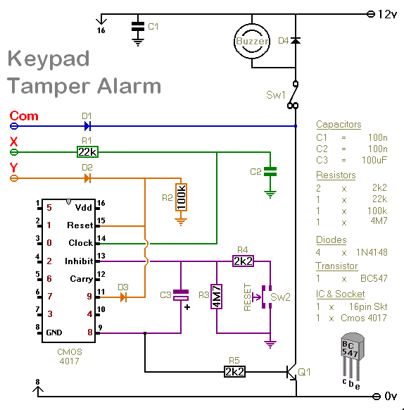
Two different control switches are provided. The first - Sw1 - simply stops the noise. Removing the lock from the keypad is left to the timer circuit. Sw1 gives you the option to silence the alarm - and still retain the keypad protection.
Sw2 shortens the time it takes for C3 to charge. It both removes the lock from the keypad - and stops the noise. Any small normally-open switch will do. If you use a magnetic reed-switch - you can hide the switch within the keypad housing - and use a magnet to reset the alarm.
Connections
There are three connections to be made between the Tamper-Alarm and the Keypad Circuit. Connect "Com" on the Tamper-Alarm Circuit to "Com" on the Keypad Circuit. Connect "X" on the Tamper-Alarm Circuit to Pin 1 of the 4081. And connect "Y" on the Tamper-Alarm Circuit to the junction of the relay coil and the collector of Q6.
Universal Keypad-Operated Switch
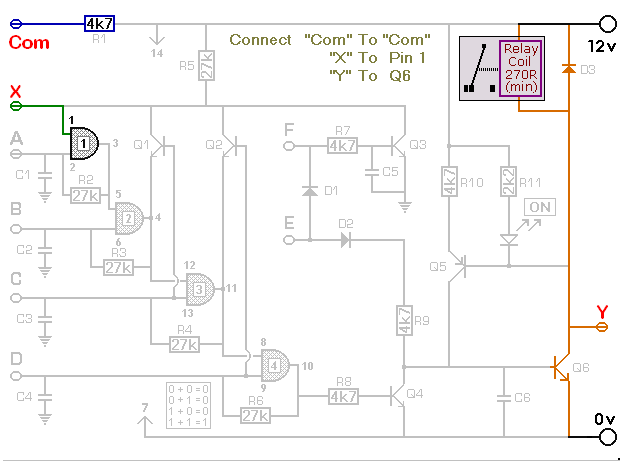
The count advances by one every time a "Wrong" key is pressed. A wrong key is any key that takes pin 1 of the 4081 low. Since "E" takes pin 1 low - "E" is a wrong key. Therefore - when you press "E" to energize the relay - the count will always advance to one. That leaves seven more wrong-key inputs before the Tamper-Alarm will activate. Note that "A" and "B" never take pin 1 low - so pressing them does not advance the count.
The support material for the Keypad Tamper-Alarm includes a complete Circuit Description - A step-by-step Guide To Construction - And details of how to Test Your Finished Board
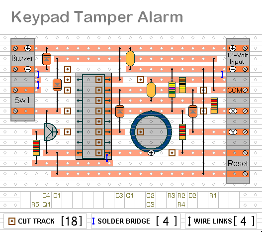
Veroboard Layout
Click Here For A Photograph Of The Prototype
 SUGGESTIONS
