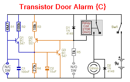
Four small battery-powered transistor alarm circuits - you can build your self - using cheap off-the-shelf components.
Parts List
|
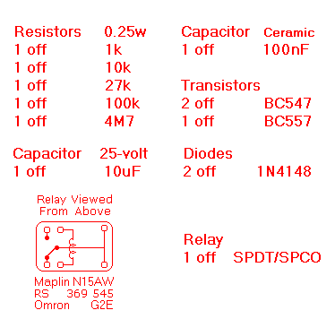
|
|
|
Construction Guide
Click here if you're new to constructing stripboard projects.
The terminals are a good set of reference points. To fit them, you may need to enlarge the holes slightly. Then turn the board over and use a felt-tip pen to mark the 7 places where the tracks are to be cut. Before you cut the tracks - double check your marks - to be certain that they are all in the right place
When you're satisfied that the pattern is right - cut the tracks. Make sure that the copper is cut all the way through. Sometimes a small strand of copper remains at the side of the cut and this will cause malfunction. Use a magnifying glass - and backlight the board. It only takes the smallest strand of copper to cause a problem. If you don't have the proper track-cutting tool - then a 6 to 8mm drill-bit will do. Just use the drill-bit as a hand tool - there's no need for a drilling machine.
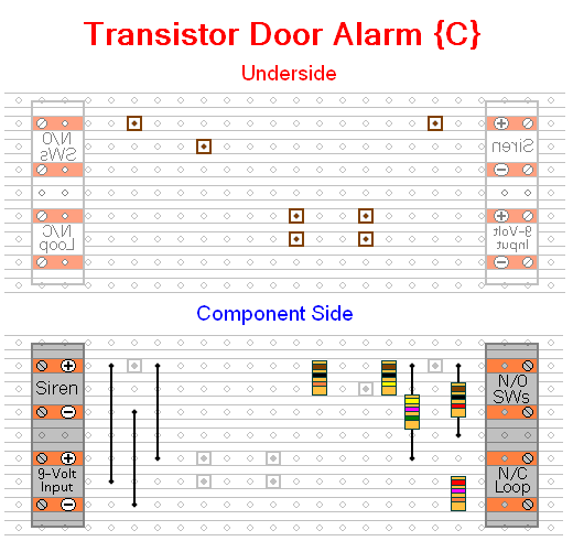
Next fit the 5 resistors and the three wire links. Use the wire you've trimmed from the resistors - to make the links. The resistors are all shown lying flat on the board. However, those connected between close or adjacent tracks are mounted standing upright.
See The Photograph Of The Prototype.
The next stage is to fit the three transistors and the two diodes. The pnp transistor (BC557) is the one with the emitter arrow coloured red. Pay particular attention to the orientation of the diodes. Note that in both cases the side with the bar is pointing up.
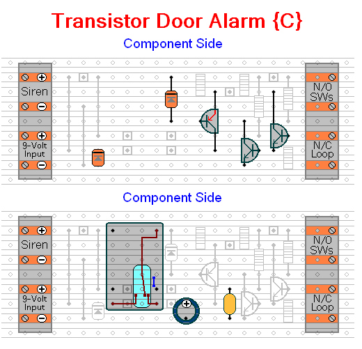
Fit the relay and the two capacitors next. Pay particular attention to the orientation of the electrolytic capacitor. Note that the positive terminal is pointing up.
Turn the board over and examine the underside carefully - to make sure that there are no unwanted solder bridges or other connections between the tracks. If you backlight the board during the examination - it makes potential problem areas easier to spot. When you are satisfied that everything is in order - add the one solder bridge (coloured blue) to the underside of the board.
You're Now Ready To Test Your Circuit
 SUGGESTIONS