Build these simple motorbike alarms yourself using veroboard and cheap off-the-shelf components. They are suitable for 6-volt as well as 12-volt systems - so they'll protect your "Classic Bike". In standby mode they use absolutely no current - so they won't drain your battery.
Introduction
The components used in the circuits should be widely available. However - none of them are critical. So if you can't find the specified parts - you're certain to find something that will do just as well.
On a modern motorcycle you would normally use a 12-volt relay and a 12-volt siren. But the circuit will work at 6-volts. So you can use it to protect your "Classic Bike". Just choose a relay and a siren suitable for the lower voltage.
Because I didn't want the circuits to drain the motorcycle battery - I designed them to have zero standby current. So you could use dry-batteries to power your alarm. This would make it more secure - because it could not be defeated by disconnecting the motorcycle battery.
It also means that the alarms may be used in situations where a power source is not readily available. For example, they could be fitted inside a computer - to sound the alarm if a thief tries to pick it up and carry it away.
Circuit No.5 - Operation
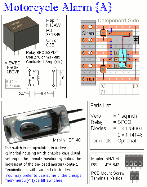
When one of the trigger-switches is closed, it connects the negative side of the relay coil to ground - and the relay energizes. The normally-open relay contacts close. This connects the negative side of the siren to ground - causing the siren to sound.
If you leave out D3 - then as soon as you re-open the trigger-switch - the relay will de-energize and the siren will turn off. But if you fit D3 - then the negative side of the relay coil will be taken to ground through D3 and the normally-open relay contacts. So when you re-open the trigger switch - the relay will remain energized - because it's connecting itself to ground through its own contacts.
It's true that D3 could be replaced by a simple link - but then the trigger-switches would be required to switch the full current drawn by the siren. The diode creates a one-way path. The trigger-switches only ever have to switch the relatively small current drawn by the relay coil. The diode confines the higher current - drawn by the siren - to the relay contacts alone.
Relay coils and some sounders produce high reverse-voltage spikes that will destroy sensitive electronic components. D1 and D2 are there to short-circuit these spikes before they can do any damage. Although there is nothing in the alarm circuit itself that could be damaged - I have no idea what other electronic equipment might be connected to the same power supply. So I included the two diodes as a precaution. If you're satisfied that there's nothing on your bike that might be damaged in this way - you can leave out the two diodes
Circuit No.5 - Parts List
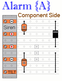
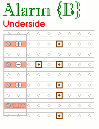
Circuit No.5 - Construction
Click here if you're new to constructing stripboard projects.
The terminals are a good set of reference points. To fit them, you may need to enlarge the holes slightly. Then turn the board over and use a felt-tip pen to mark the 3 places where the tracks are to be cut. Before you cut the tracks - double check that the marks are in the right place.
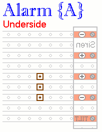
When you're satisfied that the pattern is right - cut the tracks. Make sure that the copper is cut all the way through. Sometimes a small strand of copper remains at the side of the cut and this will cause malfunction. Use a magnifying glass. It only takes the smallest strand of copper to cause a problem. If you don't have the proper track-cutting tool, then a 6 to 8mm drill-bit will do. Just use the drill-bit as a hand tool - there's no need for a drilling machine.
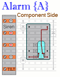
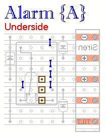
Next fit the three diodes and the wire link. Pay particular attention to the orientation of the diodes. The positive side is usually marked with a line. Note that D1 and D3 have their positive side facing the top of the board - while the positive side of D2 faces downward.
Then solder the relay into place.
Turn the board over and add the 5 solder bridges to the underside. Then double check the position and orientation of all of the components. Examine the underside of the board very carefully - to make sure that there are no unwanted solder bridges or other connections between the tracks.
Circuit No.6 - Operation
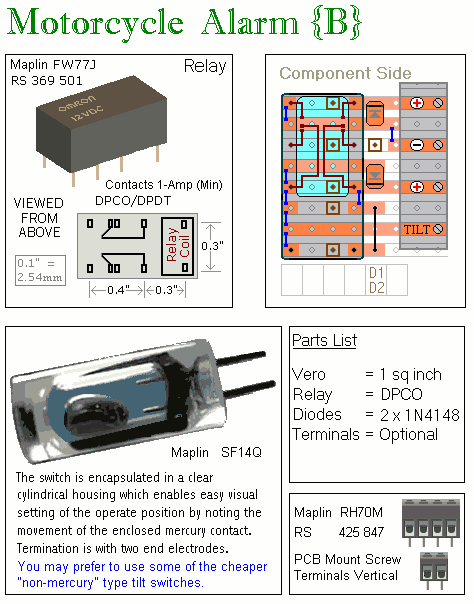
When one of the trigger-switches is closed, it connects the negative side of the relay coil to ground - and the relay energizes. The normally-open relay contacts close. This connects power to the positive side of the siren - causing the siren to sound.
If you leave out the solder-bridge in the top left-hand corner of the veroboard layout diagram - then as soon as you re-open the trigger-switch - the relay will de-energize and the siren will turn off. But if you add the solder-bridge - then the negative side of the relay coil will be taken to ground through the normally-open relay contacts. So when you re-open the trigger switch - the relay will remain energized - because it's connecting itself to ground through its own second set of contacts.
Using a double-pole relay makes installation of the alarm a little easier. One set of contacts switches the positive and the other set switches the negative. Because the siren has its positive feed switched - its negative lead doesn't need to be wired back to the circuit board. It can be connected directly to the chassis.
Relay coils and some sounders produce high reverse-voltage spikes that will destroy sensitive electronic components. D1 and D2 are there to short-circuit these spikes before they can do any damage. Although there is nothing in the alarm circuit itself that could be damaged - I have no idea what other electronic equipment might be connected to the same power supply. So I included the two diodes as a precaution. If you're satisfied that there's nothing on your bike that might be damaged in this way - you can leave out the two diodes
Circuit No.6 - Parts List
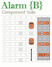
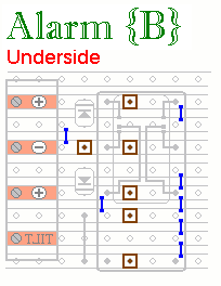
Circuit No.6 - Construction
Click here if you're new to constructing stripboard projects.
The terminals are a good set of reference points. To fit them, you may need to enlarge the holes slightly. Then turn the board over and use a felt-tip pen to mark the 6 places where the tracks are to be cut. Before you cut the tracks - double check that the marks are in the right place.
When you're satisfied that the pattern is right - cut the tracks. Make sure that the copper is cut all the way through. Sometimes a small strand of copper remains at the side of the cut and this will cause malfunction. Use a magnifying glass. It only takes the smallest strand of copper to cause a problem. If you don't have the proper track-cutting tool, then a 6 to 8mm drill-bit will do. Just use the drill-bit as a hand tool - there's no need for a drilling machine.
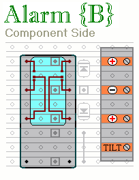
Next fit the two diodes and the wire link. Pay particular attention to the orientation of the diodes. The positive side is usually marked with a line. Note that D1 has the positive side facing the top of the board - while the positive side of D2 faces downward.
Then solder the relay into place.
Turn the board over and add the 7 solder bridges to the underside. Then double check the position and orientation of all of the components. Examine the underside of the board very carefully - to make sure that there are no unwanted solder bridges or other connections between the tracks.
General Information
In case you are not familiar with it, Stripboard or Veroboard is a board drilled with a matrix of 1mm holes spaced approximately 2.5 mm apart and joined in rows by copper strips. The pieces used have 9 rows with 9 holes in each; and measures roughly 1 square inch (2.5 cm by 2.5cm). The drawings show the boards with PCB mounting terminal blocks but - to save money and/or space - the wires may be soldered to veropins or directly to the board itself.
"Mercury Tilt Switches" are generally small glass bulbs with two contacts at one end. Inside the bulb is a "ball" of mercury. When the switch is "tilted" a few degrees off the horizontal - the mercury flows to one end and connects the contacts together. Mercury switches are expensive. You may prefer to use cheaper "non-mercury" tilt-switches.
The mercury switches are fitted so that they close when the steering is moved or when the bike is lifted off its side-stand or pushed forward off its centre-stand. The micro-switches (hinge-lever switches) are used to protect removable panels and the lids of panniers (saddlebags) etc.
The fuse MUST be fitted as close to the power source as possible. This is VERY IMPORTANT! It's there to protect the wiring - not the circuit board. Exactly how and where the alarm is fitted will depend on the make of your motorcycle. The only advice I can give is that the switches, the circuit board and the siren should be made as inaccessible as possible.
 SUGGESTIONS