The circuit uses a small single pole relay - such as the 12v Omron G2E. The coils of these low voltage DC relays behave just like resistors. I've used a 270 ohm resistor (Ry) to simulate my relay coil. The Differential Voltage Probe measures the voltage across the relay coil. And the state of the relay is determined by the level of that voltage.
The graph below represents two separate activations. The first occurs at 30 seconds - when Sw1 closes briefly. And the second occurs at 150 seconds - when Sw1 closes and remains closed. In each case - the voltage across the coil rises sharply to 12v. This causes the relay to energize - and the siren to sound.
In the case of the first activation - where Sw1 is re-opened - the siren cut-off time is short. The noise will stop after about ten seconds. Where Sw1 remains closed - the cut-off time is longer - about sixty seconds. I've just shown two activations. But the alarm will go on activating every time Sw1 closes.
Graphs
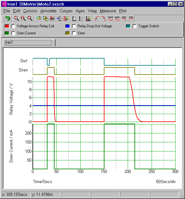
The top line represents the trigger pulses. They are produced by Sw1 - and controlled by V3 and V4. The brief On/Off pulse is provided by V3. Thirty seconds into the simulation - it rises to 5 volts. This switches Sw1 on. The switch connects C1 to ground - charges C2 - turns Q1 & Q2 on - and activates the alarm. Five seconds later - V3 re-opens Sw1. Then C2 begins to discharge slowly - through R2 & R3. And about ten seconds later - the relay drops out.
The Trigger Pulse Settings (V3)
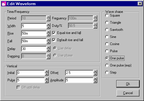
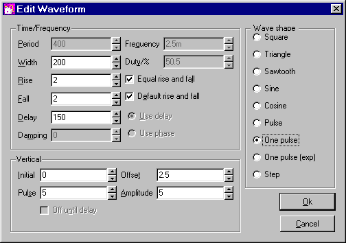
The longer - second pulse - is provided by V4. One-hundred and fifty seconds into the simulation - it rises to 5 volts. Again - this switches Sw1 on. But this time the "width" setting is two-hundred seconds. So Sw1 remains on - beyond the end of the simulation.
As before - the switch connects C1 to ground - charges C2 - turns Q1 & Q2 on - and activates the alarm. And - as before - the siren will stop when C2 discharges through R2 & R3. However - this time - C2 discharges much more slowly. It must wait while C1 completes its charge. This takes about a minute. Then the relay will drop out - and the noise will stop.
The Trigger Pulse Settings (V4)
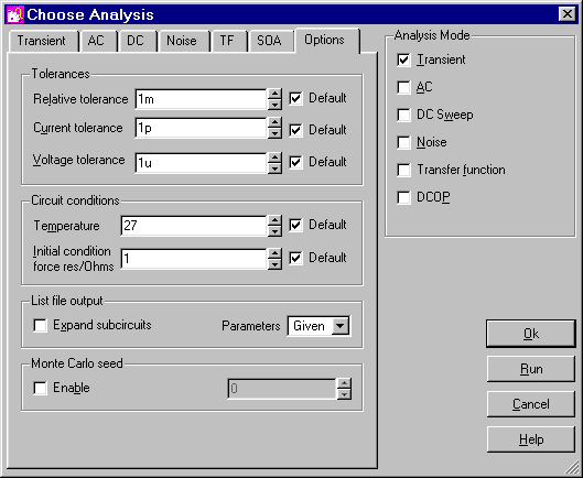
Analysis Settings
The analysis is fairly straight forward. The "Mode" should be set to "Transient". And the "Stop Time" should be long enough to allow the alarm to complete the two activations. I chose 300 seconds.
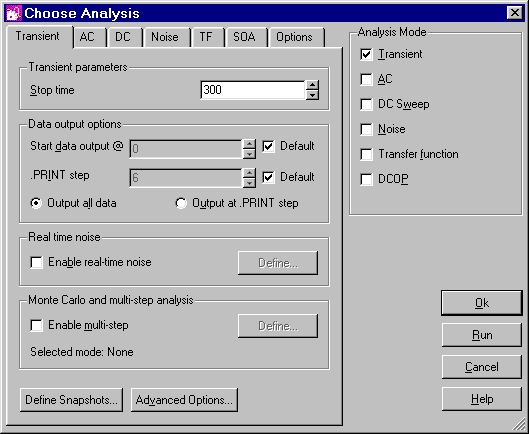
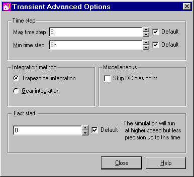
All the remaining settings are "Default". There will be times when you'll find it necessary or advantageous to change the "Tolerances" - the "Time Step" and the "Integration Method" etc. But for this circuit - the default settings are adequate.
Why Are There Diodes In Series With V3 & V4?
I wanted to switch Sw1 twice - first with the brief "On/Off" pulse - then later with the longer "On Only" pulse. So I needed two separate waveforms - from two separate waveform generators. The diodes create one-way paths. They allow both control pulses to reach Sw1 - but they prevent the individual waveform generators from shorting together.
When the V3 pulse is high - V4 is low. So the high V3 pulse would simply disappear into the low V4 generator. The converse is also true. When the V4 pulse is high - V3 is low. So the high V4 pulse would simply disappear into the low V3 generator. The diodes stop this from happening. While the V3 pulse can reach Sw1 - it cannot reach V4. And while the V4 pulse can also reach Sw1 - it cannot reach V3.