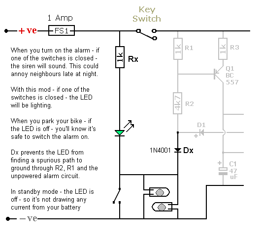
Motorcycle Alarm No.1
This diagram shows how to connect an indicator LED to the trigger switches of
Motorcycle Alarm No.1 If the LED is lighting - you know that at least one of the trigger switches is closed. So the alarm will activate if you turn it on. If the LED is not lighting - you know that all of the switches are open - and it's safe to turn the alarm on.
Click Here To Add A Separate LED To Each Trigger Switch
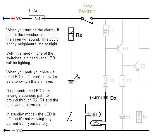
Motorcycle Alarm No.2
This diagram shows how to connect an indicator LED to the trigger switches of
Motorcycle Alarm No.2 If the LED is lighting - you know that at least one of the trigger switches is closed. So the alarm will activate if you turn it on. If the LED is not lighting - you know that all of the switches are open - and it's safe to turn the alarm on.
Click Here To Add A Separate LED To Each Trigger Switch
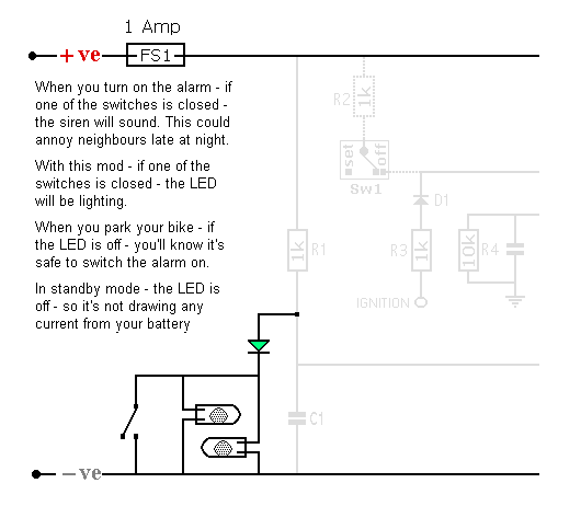
Motorcycle Alarm No.3
This diagram shows how to connect an indicator LED to the trigger switches of
Motorcycle Alarm No.3 If the LED is lighting - you know that at least one of the trigger switches is closed. So the alarm will activate if you turn it on. If the LED is not lighting - you know that all of the switches are open - and it's safe to turn the alarm on.
Click Here To Add A Separate LED To Each Trigger Switch
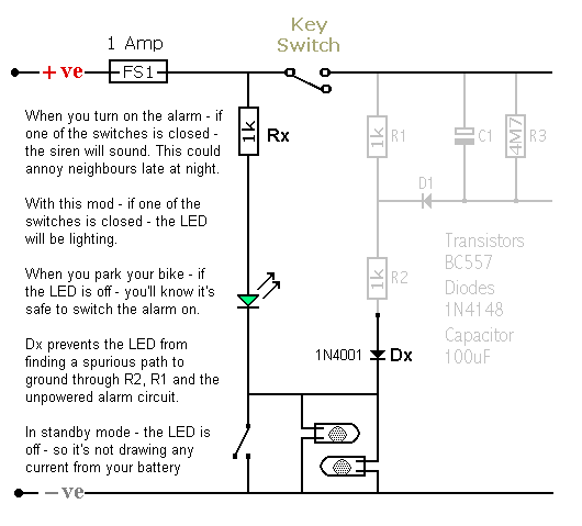
Motorcycle Alarm No.4
This diagram shows how to connect an indicator LED to the trigger switches of
Motorcycle Alarm No.4 If the LED is lighting - you know that at least one of the trigger switches is closed. So the alarm will activate if you turn it on. If the LED is not lighting - you know that all of the switches are open - and it's safe to turn the alarm on.
Click Here To Add A Separate LED To Each Trigger Switch
Add An LED To Each Switch
This diagram shows how to connect a separate indicator LED to each of the trigger switches. If an LED is lighting - you know that its corresponding trigger switch is closed. So the alarm will activate if you turn it on. But if all the LEDs are off - you know that all of the switches are open - and it's safe to turn the alarm on.
The drawing shows three switches - but the pattern should be clear. There's a resistor and LED connected between "A" and each individual switch. There's also a diode connected between "B" and each of the switches.
Click Here For A Photograph Of The Prototype LED Module.
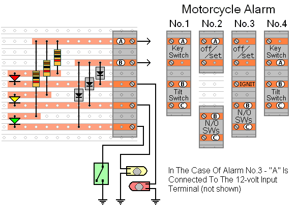
Since each of the switches is likely to be connected to a "local" earth - there may be no connections to terminal "C". In the case of
Motorcycle Alarm No.3 - "A" should be connected to the 12-volt input terminal (not shown) - situated at the top right-hand side of the circuit board.


