The circuit uses a small single pole relay - such as the Omron G2E. The coils of these low voltage DC relays behave just like resistors. I've used a 270 ohm resistor (Ry) to simulate my relay coil. The Differential Voltage Probe measures the voltage across the relay coil. And the state of the relay is determined by the level of that voltage. A similar probe indicates the state of the buzzer (Bz).
In the graph below - the horizontal green line represent the switching voltage of gate 3. In particular - it shows the voltage at which a low pin 8 becomes a high pin 8 - and vice-versa.
The red curve represents the voltage across C9. If the light from the mobile phone's display illuminates the LDR for at least 30 seconds - the red curve will cross the horizontal green line. And the gate 4 output will reset the 4017.
Graphs
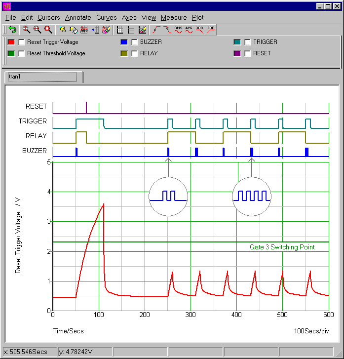
To begin with - the circuit interprets the first trigger pulse as the signal to switch ON. And its immediate reaction is to energize the relay. But when the pulse continues for over 30 seconds - the circuit recognises it as a reset signal. So gate 4 resets the 4017. And the relay de-energizes again.
The subsequent trigger pulses are all 10 seconds long. This is not long enough for the charge on C9 - to take the red curve above the horizontal green line. So the circuit interprets these shorter pulses as simple On/Off signals - and toggles the relay accordingly.
As well as providing the clock pulses that control the 4017 - the gate 1 output is also responsible for sounding the buzzer. Pin 3 supplies the power necessary to run the Q2/Q3 oscillator. The alternate pin 3 clock pulses are different lengths. The ON pulse lasts long enough to sound the buzzer twice. While the OFF pulse lasts twice as long - and sounds the buzzer four times.
The Reset Control Pulse (V2)
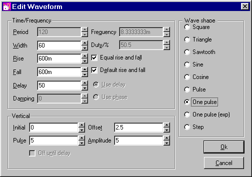
The LDR is a simple analogue switch - with its "On Resistance" set to 5k. The switch is controlled by V2. After an initial delay of 50 seconds - V2 delivers one 60 second pulse to the LDR. During the pulse - the resistance of the LDR falls to 5k.
I chose 5k because that's roughly the resistance reading I got from my LDR - while it was illuminated by my mobile phone. However - any reading below about 50k should be perfectly satisfactory.
The sudden drop in LDR resistance - takes pin 6 high - and triggers the On/Off monostable. Then about 30 seconds later - when C9 has charged through R13 - pin 8 will go high - and trigger the Reset monostable.
The On/Off Trigger Pulse Settings (V3)
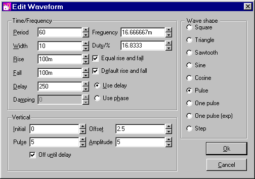
V3 also controls the LDR. After an initial delay of 250 seconds - the LDR is activated at one-minute intervals. This simulates a series of ten second calls. And the successive calls energize and de-energize the relay.
Analysis Settings
The analysis is fairly straight forward. The "Mode" should be set to "Transient". And the "Stop Time" should be long enough to allow the circuit to complete a few On/Off cycles. I chose 600 seconds.
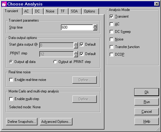
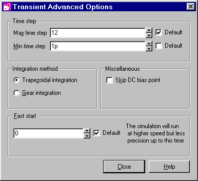
SIMetrix uses your choice of stop time to calculate some of its default settings. Here the stop time figure is relatively high. And one of the resulting default settings is too high to allow the simulation to run successfully.
In particular - the default "minimum time step" is too long. You'll find the minimum time step setting - under the "Advanced Options" button. For present purposes - the actual choice of minimum step length is not too important - provided it's short enough. So I made mine a really short one picosecond.
Why Is The Simulation 5-Volts?
The Cmos Models that come with SIMetrix 5.40 are designed for a 5-volt supply. So - to keep matters simple - I've set up a 5-volt simulation. However - the circuit will work from 5v to 15v. All you have to do is choose a relay and buzzer that are suitable for the voltage you want to use.
Why Have The Values Of R2 & R14 Been Increased?
These two resistors control the rate at which C7 charges. They set the number of flashes/beeps the circuit produces - when the relay changes state. The precise resistor values required - for any given number of flashes and beeps - depend on the characteristics of the actual components you've used. The values are particularly dependent on the switching voltage of gate 1 - and the speed of your Q2/Q3 oscillator.
The two 1M resistors used in the prototype - produced the required number of flashes/beeps. i.e. Two-On and Four-Off. However - the characteristics of the SIMetrix component models are such that - two higher value resistors were needed - in order to produce the same results.
Why Are There Diodes In Series With V2 And V3?
I wanted to switch the LDR in two different ways. I wanted to begin with a long "Reset" pulse - followed by a series of shorter "On/Off" pulses. To do this - I needed two separate waveforms - from two separate waveform generators. The diodes create one-way paths. They allow both control pulses to reach the LDR - but they prevent the individual waveform generators from shorting together.
When V2 is high - V3 is low. So the high V2 pulse would simply disappear into the low V3 generator. The converse is also true. When V3 is high - V2 is low. So the high V3 pulse would simply disappear into the low V2 generator. The extra diodes stop this from happening. While the high V2 pulse can reach the LDR - Dy prevents it from reaching V3. And while the high V3 pulse can reach the LDR - Dx prevents it from reaching V2.