All the information you need to build a simple keypad operated switch - with enhanced security.
This is a universal four-digit keypad-operated switch - with a difference. Instead of entering the security code one number at a time - the four keypad buttons must be pressed simultaneously. In other words - the four numbers must be entered in parallel.
The intruder won't know the code. He won't even know how many digits there are in the code. And he almost certainly won't know that the entire code must be entered simultaneously. Added to this - is the extra layer of security provided by the secret time-lock. After a few incorrect codes are entered - the circuit will stop responding to the keypad. And any further attempts to crack the code - will be unsuccessful.
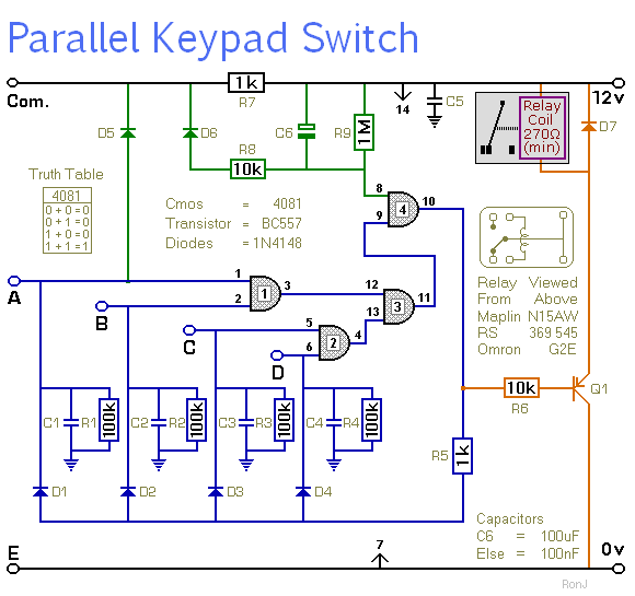
If you don't want the time-lock feature - leave out D6, C6, R8 & R9. And connect pins 8 & 9 of the IC together. If you want to use a three-digit security code - leave out D4, C4 & R4. And connect pins 5 & 6 of the IC together. Three digits are easier to enter than four.
Schematic Diagram
Click Here For A Photograph Of The Prototype.
 Do not use the "on-board" relay to switch mains voltage. The board's layout does not offer sufficient isolation between the relay contacts and the low-voltage components. If you want to switch mains voltage - mount a suitably rated relay - somewhere safe - Away From The Board.
Notes
Choose the four keys you want to use for your code - and connect them to "A B C & D". Since the keys have to be pressed simultaneously - the order in which you make the connections is irrelevant. Wire the keypad's common terminal to "Com". And connect all the remaining keys to ground. That is - to "E".
The circuit will power-up with the relay energized. When you press keys "A B C & D" simultaneously - the relay will de-energize. To energize it again - press any key not included in your code. That is - any key connected to "E".
If you want to reverse the action of the circuit - replace the PNP transistor - with an NPN transistor. If you use a BC547 instead of a BC557 - the circuit will power-up with the relay de-energized. And it will energize when you enter your code.
I used a SPCO/SPDT relay in the prototype. But you can use a multi-pole relay if it suits your application.
The Time Lock
If you make more than a couple of attempts to enter an incorrect code - the circuit will lock you out. How quickly it does so - depends on the value of R8. If you are locked out - you must wait for a minute or so - before you enter the correct code. How long you have to wait - depends mainly on the value of R9. If you don't wait long enough - and you keep trying to enter incorrect codes - the circuit will keep you locked out.
The Keypad
The total number of different codes - or key patterns - available depends on the number of keys in your pad. With a 12-key pad - there's a choice of 495 different groups of four keys. If you want a more secure code - use a bigger keypad. A 16-key pad lets you choose from 1820 different groups of four.
You can also split the code between two separate keypads. If you mount the keypads far enough apart - two people will have to be present in order to operate the switch. And by using the technique described on the Support Page - under the heading - General Information - each person can have his own unique three-digit security code.
The keypad itself must be the kind with a common terminal - and a separate connection for each key. On a 12-key pad - look for 13 terminals. The matrix type with 7 or 8 terminals will NOT do. The Support Material for this circuit includes details of how to make a suitable keypad. It also includes a detailed circuit description - a parts list - a step-by-step guide to the construction of the circuit board - and more.
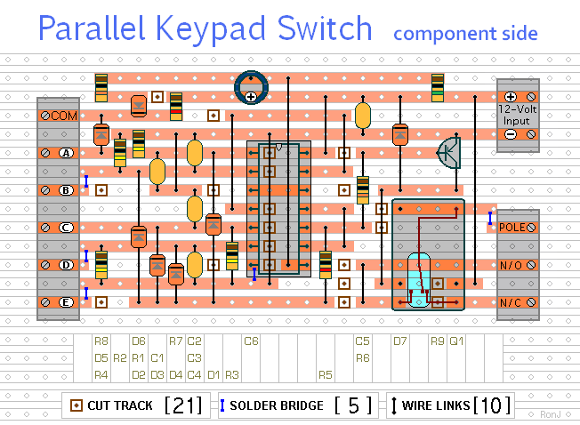
Veroboard Layout
Click Here For A Photograph Of The Prototype.
 SUGGESTIONS
