This circuit has an adjustable output timer that will re-trigger at regular intervals. Build it yourself - using basic Cmos gates.
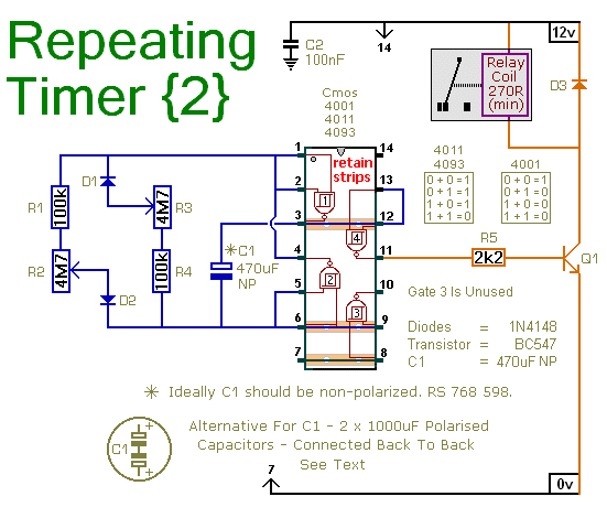
This circuit is based on a simple asymmetric oscillator. The length of time the relay remains energized - and the length of time it remains de-energized - are set independently. With the component values shown in the diagram - both periods are adjustable from about 1 to 30 minutes.
Schematic Diagram
Click Here For A Photograph Of The Prototype

Setting The Timer
The frequency of the Astable Oscillator depends on the value of C1 and the speed at which it charges and discharges through the resistor network. The length of time the relay remains energized is controlled by R2. And the length of the time it remains de-energized is controlled by R3.
Owing to manufacturing tolerances - the precise length of the time periods available depends on the characteristics of the actual components you've used. R1 & R4 set the minimum period lengths at about 1-minute - while R2 & R3 set the maximum periods at about 30-minutes. You can choose component values that suit your own requirements. If your time periods don't need to be too precise - and more-or-less is close enough - you can leave out the pots altogether - and simply rely on R1 & R4 to set the times.
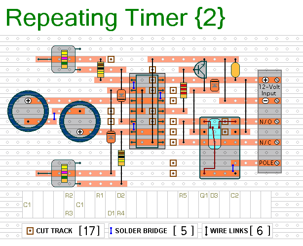
 Do not use the "on-board" relay to switch mains voltage. The board's layout does not offer sufficient isolation between the relay contacts and the low-voltage components. If you want to switch mains voltage - mount a suitably rated relay somewhere safe - Away From The Board. I've used a SPCO/SPDT relay - but you can use a multi-pole relay if it suits your application.
Alternative Capacitor
A regular electrolytic capacitor is polarised. If the charge on its plates is the wrong way round - DC current will flow through the capacitor. If the current is high enough - the capacitor will heat up and explode.
When the oscillator is running - the polarity of the charge on C1 keeps reversing. So C1 needs to be non-polarised. However - you can simulate a non-polarised 470uF capacitor by connecting two 1000uF polarised capacitors back to back - as shown. How and why this works is explained in the Detailed Circuit Description. Because non-polarised capacitors aren't widely available - the prototype was built using two polarised capacitors.
Veroboard Layout
Click Here For A Photograph Of The Prototype

The timer is designed for a 12-volt power supply. However - it will work at anything from 5 to 15-volts. All you need do is select a relay to suit your supply voltage. The Cmos gates are being used as simple inverters. So - although I've used a Cmos 4093 in the circuit diagram - a Cmos 4001 or Cmos 4011 will work just as well.
The Support Material for this circuit includes a step-by-step guide to the construction of the circuit-board - a parts list - a detailed circuit description - and more.
 SUGGESTIONS
 SUGGESTIONS


