This circuit has an adjustable output timer that will re-trigger at regular intervals. The lengths of both the ON and the OFF periods - are independently adjustable.
This timer is based on a simple
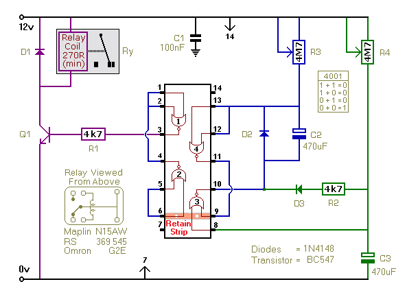
Monostable Circuit. The length of time the relay remains energized - the ON period - is controlled by the values of R3 & C2. And the length of time the relay remains de-energized - the OFF period - is controlled by the values of R4 & C3. With the component values shown - periods of up to 30 minutes are available.
Schematic Diagram
Click Here For A Photograph Of The Prototype
Setting The Timer
The length of time the relay remains energized is controlled by the values of R3 & C2. And the length of the time the relay remains de-energized is controlled by the values of R4 & C3. Owing to manufacturing tolerances - the precise length of the time periods available depends on the characteristics of the actual components you've used.
You can choose component values that suit your own requirements. You should get about 70 seconds for every 1Meg/100uF. So 4M7 & 100uF will give about 6 minutes. And 4M7 & 1000uF will give about an hour. If your time periods don't need to be too precise - and more-or-less is close enough - you can replace the pots with fixed resistors.

Do not use the "on-board" relay to switch mains voltage. The board's layout does not offer sufficient isolation between the relay contacts and the low-voltage components. If you want to switch mains voltage - mount a suitably rated relay somewhere safe -
Away From The Board. I've used a SPCO/SPDT relay - but you can use a multi-pole relay if it suits your application.
Veroboard Layout
Click Here For A Photograph Of The Prototype
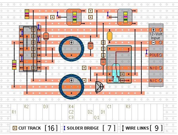
The timer is designed for a 12-volt power supply. However - it will work at anything from 5 to 15-volts. All you need do is select a relay to suit your supply voltage. The
Support Material for this circuit includes a step-by-step guide to the construction of the circuit-board - a parts list - a detailed circuit description - and more.
 SUGGESTIONS
