Build this SCR Based DIY Burglar Alarm System using cheap off-the-shelf components. It has automatic Exit and Entry delays - and timed Bell cut-off. Its modular construction allows you to add as many zones as you like. It has provision for normally-open and normally-closed input devices such as Magnetic-Reed contacts - Foil Tape - PIRs - pressure mats etc.
Detailed Circuit Description
This is a simple SCR based burglar alarm circuit. Its features include automatic Exit and Entry delays - together with a timed Bell cut-off and Reset. It's designed to be used with the usual types of normally-closed input devices such as - magnetic-reed contacts - micro switches - foil tape - and PIRs.
The basic alarm has a single zone with "Exit/Entry" delays. This will be adequate in many situations. However - larger buildings are better divided into zones. The modular design means that you can Add Any Number Of Zones to the system. These "Instant" zones may be triggered by normally-open as well as normally-closed input devices.
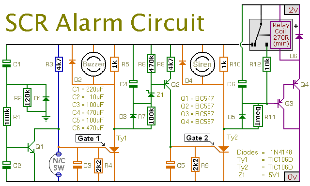
Schematic Diagram
Click Here For A Photograph Of The Prototype.
It's easy to use. When you switch on the alarm - you have about 30 seconds to leave the building. When you return and open the door - the Buzzer will sound. You have about 30 seconds to switch off the alarm. If you fail to do so - the Siren will sound.
After about 10 minutes - the alarm will attempt to reset itself. If the trigger circuit has been restored - the attempt will be successful. But - if the loop is still open - the attempt will fail - and the alarm will re-activate. Of course - you can turn the Siren off at any time by switching off the alarm.
A conventional bell uses up to about 400ma. An electronic siren generally uses less. If you intend to draw a heavier current from either the Buzzer or Siren terminals - the SCR in question will need to be bolted to a metal heatsink - and the relay contacts may need upgrading.
If you don't want the timed "cut-off and reset" feature - leave out D5, D6, R11, R12, Q3, Q4, C6 and the Relay.
Because of manufacturing tolerances - the precise length of any delay depends on the characteristics of the actual components you've used in your circuit. But - to some degree - by altering the values of R2, R7 & R11 you can adjust the Exit, Entry and Reset times to suit your requirements. Increasing the values increases the time - and vice-versa.
The Support Material for this alarm includes a detailed circuit description - a parts list - a step-by-step guide to construction - and more.
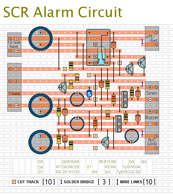
Stripboard Layout
Click Here For A Photograph Of The Prototype.
 SUGGESTIONS
