| Build this DIY mains or battery powered Burglar Alarm System using cheap off-the-shelf components. It has automatic Exit and Entry delays - and a timed bell cut-off. Use it in your home - small business premises - garage - shed - lock-up etc. It has provision for normally-closed input devices such as Magnetic-Reed contacts - Foil Tape - PIRs etc. |
|---|
Detailed Circuit Description
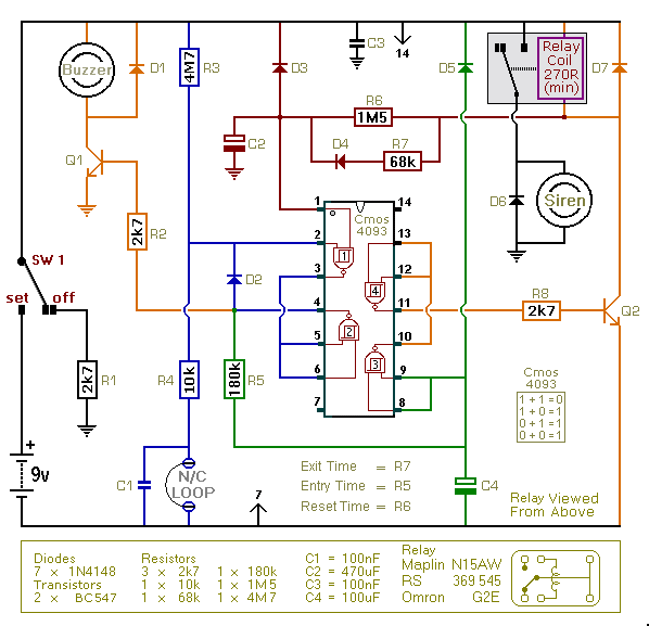
This is an enhanced version of the simple Garage/Shed Alarm. The Entry and Exit delays have been increased to about 30-seconds - and I've added a timed Siren cut-off and automatic Reset. I've also replaced the LED with an entry Buzzer. These enhancements mean that the new version will have a much wider application.
The circuit is designed to be used with the usual types of normally-closed input devices such as - magnetic-reed contacts - micro switches - foil tape - and PIRs.
Although it can be mains powered - the extremely small standby current makes it ideal for battery-powered operation. I've used a 9-volt battery in the diagram - but the circuit will work at anything from 5 to 15-volts. Just choose a Relay, Buzzer and Siren suitable for the voltage you want to use.
Schematic Diagram
Click Here For A Photograph Of The Prototype.

To set the alarm - move SW1 to the "set" position. You now have about 30 seconds to leave the building. When you return and open the door - the Buzzer will sound. You then have about 30 seconds to move SW1 to the "off" position. If you fail to do so - the relay will energize and the Siren will sound.
After about 10-minutes the alarm will attempt to reset itself. If the trigger circuit has been restored - the attempt will be successful. But if the loop is still open - the attempt will fail - and the alarm will re-activate. The circuit will go on trying to reset itself about every five-minutes thereafter - until the trigger circuit has been restored - or the alarm is switched off.
If a 1M5 resistor is not available - use a 1M and a 470k resistor connected in series. That's what I did. Because of manufacturing tolerances - the precise length of any delay depends on the characteristics of the actual components you've used in your circuit. But by altering the values of R5, R6 & R7 you can adjust the Entry, Reset & Exit times to suit your requirements. Increasing the values increases the time - and vice-versa.
The circuit works best with a Cmos 4093. The Cmos 4093 is the Schmidt-Trigger version of the 4011. While its logic is identical to that of the 4011 - what makes it different is a property known as "Hysteresis". The circuit will work with a 4011. But - because the 4011 does not posses hysteresis - it will not work as well.
The Support Material includes an explanation of hysteresis - a complete circuit description - a parts list - a step-by-step guide to construction - and more.
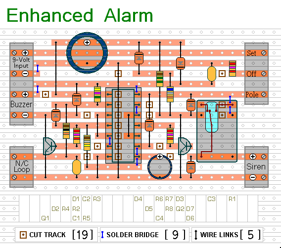
Stripboard Layout
Click Here For A Photograph Of The Prototype.

Step-By-Step Construction Guide
 SUGGESTIONS
 SUGGESTIONS

