| Full details of how to build a simple Code Operated Multi-Pole Switch - using veroboard and cheap off-theshelf components. |
|---|
 Do not use the "on-board" relay to switch mains voltage. The board's layout does not offer sufficient isolation between the relay contacts and the low-voltage components. If you want to switch mains voltage - mount the relay somewhere safe - Away From The Board.
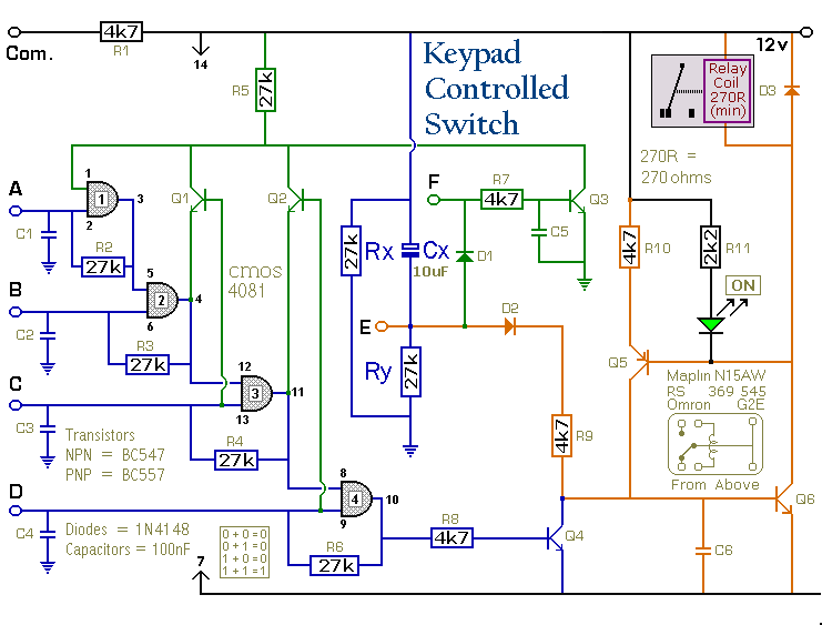
Introduction
The following modifications will change the way the Universal Keypad Operated Switch functions. I don't have Stripboard Layouts for the circuits - but the modifications are quite small. I have tried them out on the prototype - and they work.
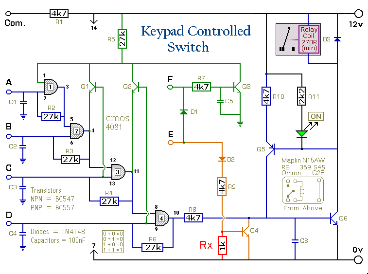
Power-Up With The Relay Energized
This circuit is exactly the same as the original - except for the addition of the three extra components - Rx, Ry & Cx.
At power-up, Cx is in a discharged state - and current flowing through it turns Q6 on - just as though "E" has been pressed. This is only a brief pulse because Cx charges quickly and "E" goes low. But the pulse is long enough to energize the relay - so that Q5 & R10 can take over and hold it in. You can now enter the code to de-energize the relay; and press "E" - just as before - to energize it again.
The two resistors are there to discharge the capacitor when the power is turned off - so that it will be ready to conduct when power is re-applied. Given enough time, Cx would probably discharge on its own - eventually. But to make it available for immediate re-use - it must be provided with its own discharge path.
Simply connecting a resistor across Cx will not do, because that would take "E" permanently high - so Q3 would be switched-on through D1 - and the "Turn-off" code would not work. That's why the discharge resistor is split in two - it makes the connection between the plates of the capacitor via the negative rail. In this way, the discharge path only exists when the power is disconnected.
With 27k resistors and a 10uF capacitor, you can re-apply the power immediately - and the circuit will start-up with the relay energized. If you use larger values for the resistors and capacitor - the discharge is slower. So you have to wait a bit before you re-connect the power.
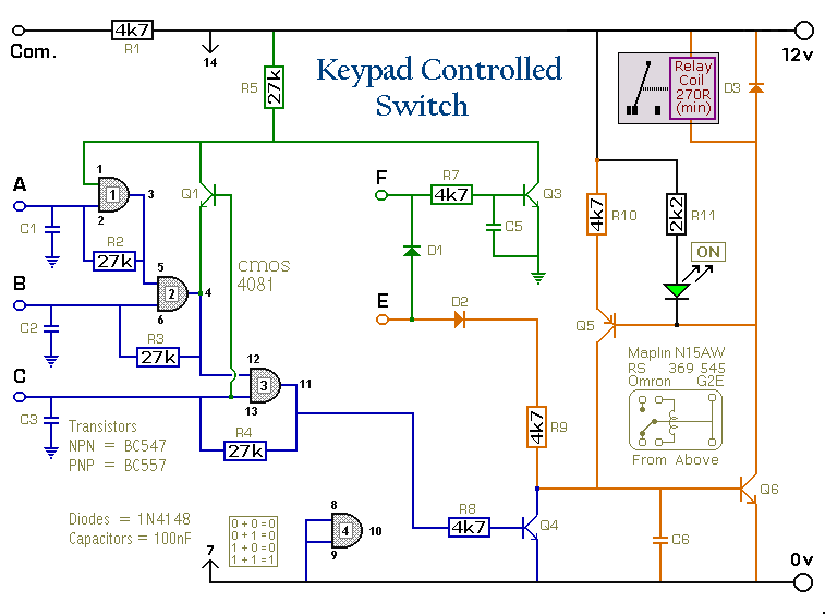
Reverse The Operation Of The Circuit
Again, this circuit is exactly the same as the original - except that now "E" controls Q4 - and Pin 10 controls Q6. This means that you have to enter the code in order to energize the relay - but you can de-energize it by simply pressing "E".
All you need do is move R8 from the base of Q4 to the base of Q6 - and move R9 from the base of Q6 to the base of Q4. Then add the extra resistor - Rx - to keep Q4 switched off when it's not needed.
The Three-Digit Keypad Operated Switch
This is a simplified version of the circuit offering 1320 different three-digit codes with a 12-key pad. Just like the original - it will power-up with the relay de-energized. Pressing "E" energizes the relay - and it's de-energized by entering the code. However, it should be possible to carry out the above two modifications - and change the way it functions.
Universal Keypad Switch - Support Material
 SUGGESTIONS
