I used to design my breadboard layouts "on the fly". I always ended up with a real mess. And it took me forever to find the (inevitable) mistakes. That's why I've adapted my
Stripboard Design Technique - for the breadboard. I know of three different styles of breadboard - and I've included a template for each in the
Resource File. If your breadboard is not there - please let me know.
You'll need a programme called Inkscape. It's free - and it's available for Windows, Linux and Mac. To get your copy - go to
Cnet.Com. Enter the word "Inkscape" into the search box. And download the version you require. I developed the templates on Linux - using the
Ubuntu version of Inkscape. And I've tested them on the Windows version. But I haven't tried them out on the Mac version.
The
Resource File includes a variety of component shapes. For convenience - many of those shapes are already on the templates. And you can use "Drag and Drop" to add the remaining shapes - as and when required.
All you have to do - is arrange the parts into a satisfactory layout. It's a bit like solving a puzzle. There's no single correct solution to the puzzle. You just have to produce a layout with which you are satisfied. I suggest you use short straight links. Then any subsequent troubleshooting will be a whole lot easier.
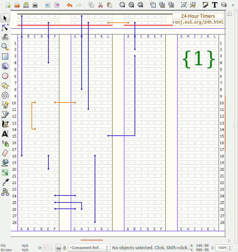
I've included some sample layouts in the
Resource File. They've all been built and tested. The layout above is for one of my
Two 24-Hour Timers. And the remaining samples are for my
Motorcycle Alarm No.2 and my
Two-Zone Alarm. You can pull all of the layouts apart - to see how they're made.
24-Hour Timer No.1 - Photo
I wanted to make the photo as clear as possible. So to keep my layout tidy - I shortened some of my component leads. If you're going to reuse the breadboard components when you build your finished circuit board - don't cut the leads short at this stage.
The links are reusable. So take a little time and care when making them. I make my links from telephone cable - the kind used indoors to wire phone sockets
Stretching The Core will straighten the wire - and loosen the insulation. Strip the ends by sliding the insulation to one side - and snipping off the excess.
Hiding Layers
There are eight layers in the template - from the breadboard pattern at the back - to the component reference numbers at the front. And most of the time - you can ignore them completely.
However - sometimes it's helpful to "hide" some of the layers. For example - when you're actually building your breadboard layout - you can remove the distractions - and concentrate solely on fitting the links.

The eight layers are listed in the menu box on the bottom status bar ("Component Ref."). One at a time - select the layers you want to hide. Then click on the small "eye" to the left of the box. The eye will close - and the selected layer will disappear.
Importing Parts
To import a new part from the resource folders - first select the correct destination layer - then "Drag & Drop" the part into the template. If you accidentally drop the part into the wrong layer - use "Cut & Paste" to move it to the right layer.
When you drop the part into the window - you'll be asked to make a choice. Always choose the "embed" option - it will make your file portable. However - it will also make your file larger. To reduce the file size - delete all of the unnecessary parts from the template.
If You Want To Re-Size A Component
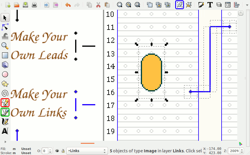
When you click on an object - it will be surrounded by eight small black arrows (ceramic capacitor below). If you want to change its size - you can stretch it in any direction - by pulling on one or more of these arrows.
However - with one exception - the objects in the
Resource File can always be used at their original size. If you have physically larger components - like higher value capacitors - just leave extra space around them.

The exception is the short wires used to "Make Your Own" leads and links. If you need to create longer or angled leads or links - stretch the short wires to fit. And use the small dots to finish off the two ends. To merge the new link/lead into a single item - use the blue (group) button above.
If you want to draw more ambitious (curved or circuitous) links and leads - you can use the green button on the left. Or you could simply draw them freehand - using the red button.
If You Want To Create A New Object
The objects in the
Resource File - snap to an invisible (11 pixel) grid pattern - on the template. That's what makes them easy to place accurately. You can draw new objects with any Paint type programme. The height and the width of each drawing - should be a multiple of 22 pixels. For example - the ceramic capacitors are 22 x 44 - the transistors are 44 x 44 - and the big relays are 132 x 88.
As you can see from the ceramic capacitor above - it's more than likely that you'll have some empty background left over. And this will have to be made transparent. I drew my parts with a Linux paint programme (
KolourPaint). And I was able to use the "Fill" tool - to make my backgrounds transparent.
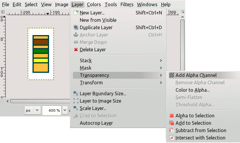
If your paint programme doesn't have a "Transparent Fill" option - you can use the free
Gimp programme to delete your backgrounds. Open your finished drawing with Gimp. And under "Layer" and "Transparency" -
click on "Add Alpha Channel". Nothing will appear to happen. It just prepares your image for the next step.

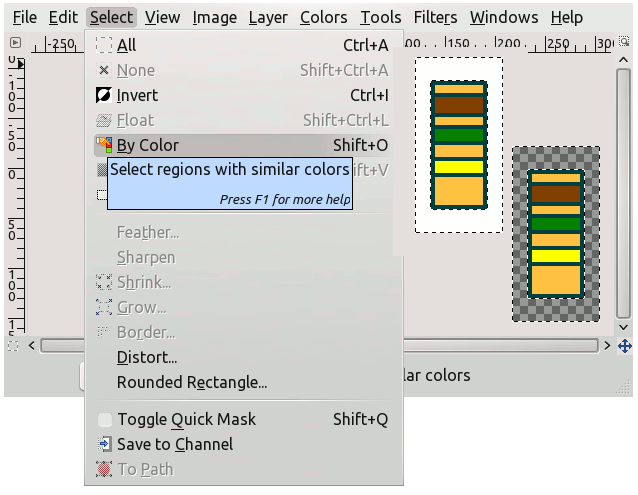
The next step is to choose "Select - By Color". Then click on the unwanted white
background - in order to select it. And press "Delete" on your keyboard - to remove it. Save your
finished component as a GIF or a PNG. For simple drawings such as these - the PNGs
usually have a smaller file size.

The background area still exists. You'll see its outline every time you select the object. The exact position of the visible component - within the invisible background - will determine how your new part aligns with the underlying breadboard pattern. In other words - if your new component doesn't snap neatly into place - try moving it to a different position - within the invisible background.
It should be easy to tell in which direction - and by how much - the component needs to be moved. If you find that you can't actually reach the right spot - the invisible background itself is probably too small. Try adding another 22 pixels to the height and/or the width of your drawing. Note that if you create or expose a fresh area of background - it too will have to be deleted.