I've added a second template - and some extra component shapes to the Resource File. The original template (below) is still there. But you should find the new one more convenient to use. You'll need a programme called Inkscape. It's free - and it's available for Windows, Linux and Mac. To download a copy - go to Cnet.Com - and enter the word "Inkscape" into the search box.
Partial View Of The Template

The method requires you to arrange the component shapes into a
satisfactory stripboard layout. It's a bit like solving a puzzle. There's no
single correct solution to the puzzle. You just have to produce a layout with
which you are satisfied.
To illustrate how the system works - I've included two sample layouts in the Resource File. The smaller layout (above) is
for my Door Alarm. And the larger layout is for my
Repeating Timer No.8. You can pull both of the
layouts apart - to see how they're made.
Photo Of The Door Alarm
Use Your Mouse Wheel To Zoom
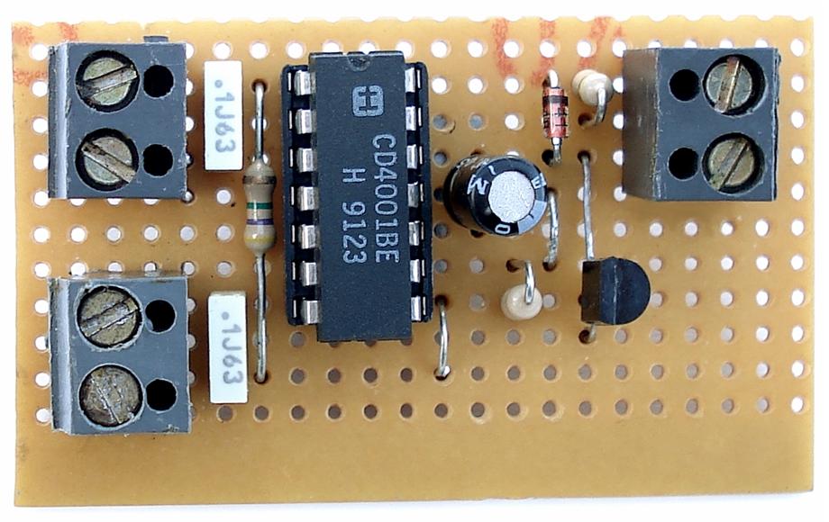
Image Magnifier Courtesy Of DynamicDrive.Com
The Resource Material
The Resource File includes most of the
components shapes I use in my layouts. They are distributed among a number of
different folders. And the name of each folder is an indication as to its
contents. You are of course free to add your own shapes to the file.
The Inkscape files have the suffix "svg". And these are the ones you will normally use. However - I have also successfully tested the same technique - with Xara Xtreme. And the various component shapes can be used with many other graphics programmes - such as Gimp.
Since I had the three "xar" files - I thought I might as well include them in the resource material. However - Xara is only free for Linux. And my copy of the programme has a couple of minor but annoying issues. So - if you're not already using Xara - I suggest you go with Inkscape instead.
Importing Parts
The resource material includes a variety of component shapes. For convenience -
many of those shapes are already included on the template itself. And you can
drag and drop the remaining shapes - as and when required - into the template
window.
There are six layers in the template - from the vero pattern at the back - to the labels at the front. They are listed in the menu box on the bottom status bar. "TrackColour" is selected below.
To import a new part from the resource folders - first select the correct destination layer. Then "Drag & Drop" the part into the template window. If you accidentally drop the part into the wrong layer - use "Cut & Paste" to move it to the right layer.
When you drop the part into the window - you'll be asked to make a choice. Always choose the "embed" option. It will make your file portable. However - it will also make your file larger. To reduce the file size - delete all of the unnecessary parts from the template.
Re-Sizing Components
Practically all of the objects in the Resource
File are intended to be used at their original size. However - there are
a few exceptions to this rule. Note that when you click on an individual object
- it will be surrounded by eight small black arrows (see the diagram below). You
can stretch the object in each direction - by pulling on one of the arrows.
The most common exception to the no-resize rule - is the track fill colour. It marks out the active sections of the tracks. It helps to identify where the tracks need to be cut. It also reveals those sections of track that are still free - and so available for use. Simply position one of the small colour segment on to the track concerned. Then stretched it lengthwise - until it occupies the whole of the active portion.
The second exception is the short wires - located on the template - next to the leads and links. The range of ready-made leads and links will span a distance of up to 22 tracks. If you need to span more than 22 tracks - stretch the short wire to fit. Then finish it off with a couple of the accompanying small dots.
The third exception will only arise if your circuit calls for physically larger
components - such as higher wattage resistors - or higher value capacitors.
Instead of simply leaving extra space - or creating the larger image yourself -
you could stretch an existing shape to suit.

Creating New Objects
The objects in the Resource File - snap to an invisible (11 pixel) grid pattern - on the template. That's what makes them easy to place accurately. You can draw new objects with any Paint type programme. The height and the width of each drawing - should be a multiple of 22 pixels. For example - the
transistors are 44 x 44 - the track colour segments are 22 x 44 - and the large relay
is 132 x 88.
As you can see from the selected items above - it's more than
likely that you'll have some empty background left over. And this will have to
be made transparent. I drew my parts with a Linux paint programme ( KolourPaint). And I was able to use the "Fill" tool - to make my backgrounds transparent.
If your paint programme doesn't have a "Transparent Fill" option - you can use the free Gimp programme to remove your backgrounds. Open your completed drawing with Gimp. And - under "Layer" and "Transparency" -
click on "Add Alpha Channel". Nothing will appear to happen. But your image will
be prepared for the next step.

The next step is to choose "Select - By Color". Then click on the unwanted white
background - in order to select it. And press "Delete" on your keyboard to remove it. Save your
finished drawing as a GIF or a PNG. For simple drawings such as these - the PNGs
usually have a smaller file size.

The background area still exists. You'll see its outline every time you select the object. The exact position of the visible component - within the invisible background - will determine how your new part aligns with the underlying stripboard pattern. In other words - if your new component doesn't snap neatly into place - try moving it to a different position - within the invisible background.
It should be easy to tell in which direction - and by how much - the component needs to be moved. If you find that you can't actually reach the right spot - the invisible background itself is probably too small. Try adding another 22 pixels to the height and/or the width of your drawing. Note that if you create or expose a fresh area of background - it too will have to be deleted.
Download The Resources File
| 

