This is a simple - easy to build - alarm circuit. For power - I used a small 9-volt battery. But the circuit itself will work from 5 to 15-volts - just choose a buzzer that's suitable for the voltage you're using. The standby current is virtually zero - so the battery life is good.
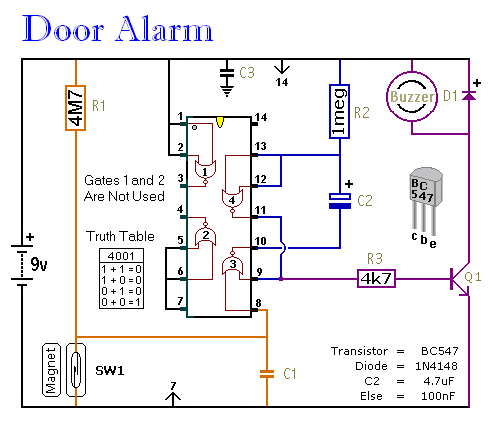
Schematic Diagram
Click Here For A Photograph Of The Prototype.
Notes
If SW1 is fitted to a door - every time the door opens - the Buzzer will give a short beep. In an unattended shop - or reception area - the sound of the beep will alert you to the fact that you have a customer. How long the output lasts depends on the values of R2 and C2. With the values shown - it will last for somewhere between 3 and 5 seconds.
But - by increasing these values - you can achieve an output time of up to half-an-hour or more. So if you replace the Buzzer with a relay - and use the relay to switch a Siren - you have a Simple Intruder Alarm that you can fit almost anywhere.
I've drawn SW1 as a magnetic-reed switch - but you can use any type of switch that suits your application. If you have more than one door or window to protect - you can use more than one switch. Just wire all of your switches in series.
Changing the Output Time
Generally speaking - the length of the output time is proportional to the values of R2 and C2. In other words, if you double the value of either R2 or C2 - you will double the output time. If you halve the value of either R2 or C2 - you will halve the output time.
For example, if you replace R2 with a 4M7 resistor you will increase the output time by a factor of about 5. If you replace C2 with a 470uF capacitor you will increase the output time by a factor of about 100. If you use both a 4M7 resistor and a 470uF capacitor together, you will increase the time by a factor of about 5 X 100 = 500. This should give you an output of around half-an-hour or more.
If you want an accurate output time - use a variable-resistor (or preset) in place of R2. Then simply adjust the resistor until you get the output time you require.
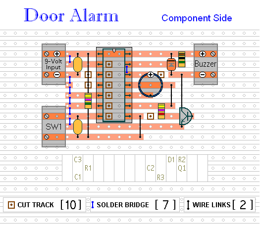
Veroboard Layout
Click Here For A Photograph Of The Prototype.
The
Support Material for this circuit includes a parts list - a detailed circuit description - a step-by-step guide to construction and details of
How To Test Your Finished Alarm.
If you're new to using Cmos ICs - and you'd like to know more about how they work - take a look at my introduction to
The Cmos 4001. It makes use of the present Door Alarm Circuit to explain - in detail - just how the IC operates.
Door Alarm - Circuit Simulation