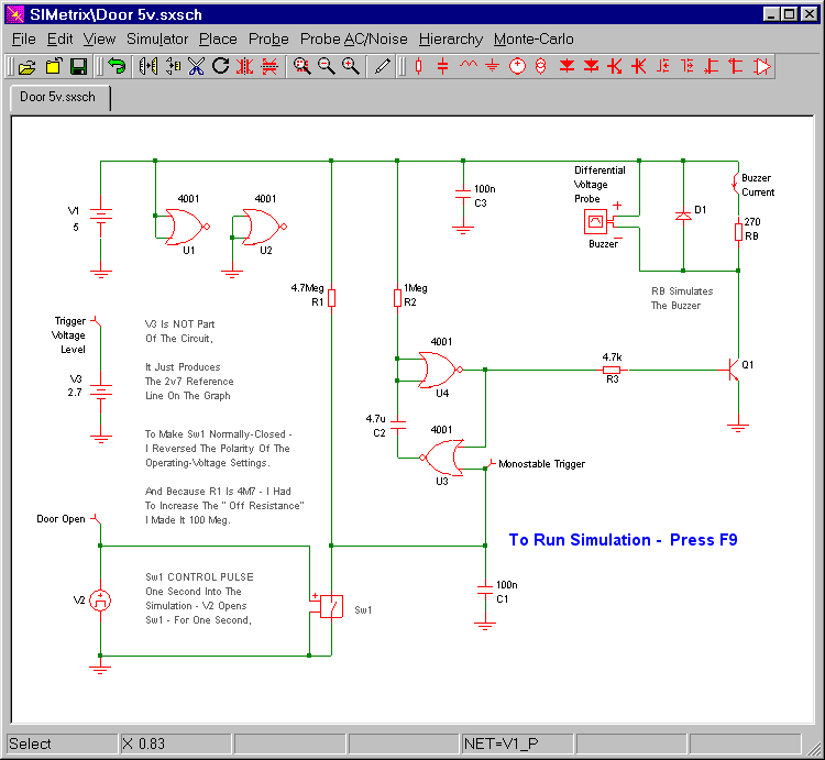
The circuit uses a small piezo buzzer. But you can also connect the coil of a small relay to the buzzer terminals. I've used a 270 ohm resistor (RB) to simulate my buzzer and/or relay coil. The differential voltage probe measures the voltage across the resistor. And the state of the buzzer / relay - is determined by the level of that voltage.
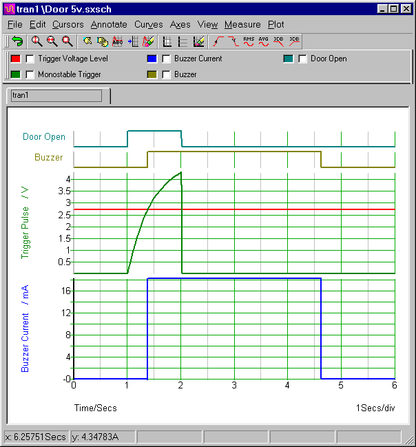
In the graph below - the horizontal red line represents the switching voltage of gate 3. When the door switch opens - R1 begins to charge C1 - and the voltage on pin 8 - the green line - starts to rise. When it crosses the red line - the buzzer sounds. It will go on sounding until R2 charges C2 - and takes the inputs of gate 4 high. With the component values shown - this takes about 3 seconds. Then the gate 4 output will go low - and the buzzer will switch off. The current flowing through the buzzer - RB - is represented by the bottom blue line. It's About 18 mA.
Graphs
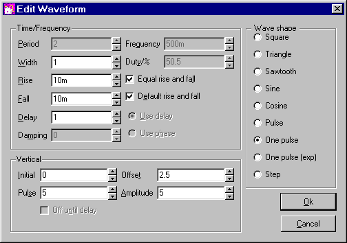
The green monostable trigger pulse is produced by Sw1 & V2. In standby mode - V2 is at zero volts - and Sw1 is closed. One second into the simulation - V2 rises sharply to five volts - and remains there for one second. The high V2 opens Sw1. And the R1 current - that Sw1 had been diverting to ground - charges C1 instead. This takes pin 8 high - and triggers the monostable.
The Trigger Pulse Settings (V2)
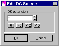
Power Supply Setting
The default power source is 5vdc. If you ever need to change that value - select the power source symbol (e.g. V1 in the schematic) - and press F7. Then change the contents of the "Parameters" window - by typing in your new value. Alternatively - you can simply use one of the preset buttons provided.
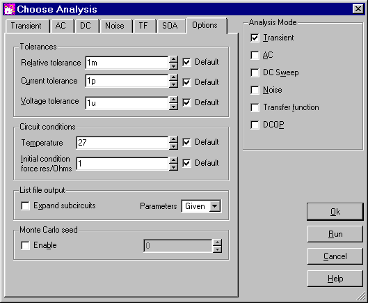
Analysis Settings
The analysis is fairly straight forward. The "Mode" should be set to "Transient". And the "Stop Time" should be long enough to allow the alarm to complete one "activation and reset" cycle. I chose six seconds.
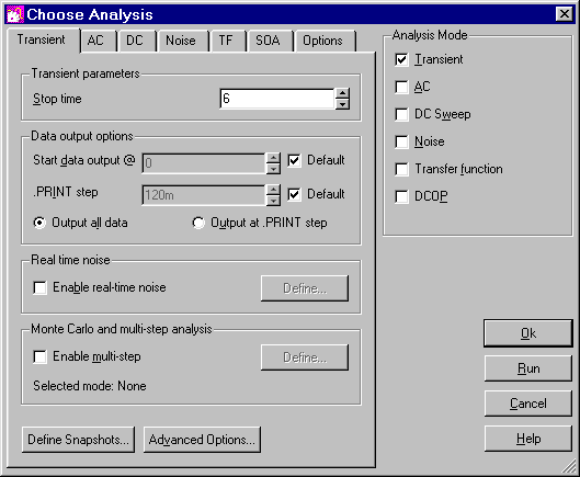
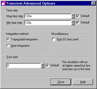
All the remaining settings are "Default". There will be times when you'll find it necessary or advantageous to change the "Tolerances" - the "Integration Method" - the "Time Step" etc. But for this circuit - the default settings are all adequate.
Why Is The Simulation 5-Volts?
The Cmos Models that come with SIMetrix 5.40 are designed for a 5-volt supply. And, to keep matters simple, I've set up a 5-volt simulation. However - the alarm itself is designed to work over a range of supply voltages. So included in the
Download Material - you'll find both 9v and 12v simulations. To run these extra simulations successfully - you'll need to install my 9v and 12v Cmos models. This is very easy. Simply drag and drop the "MyMods.lb" file into the small "SIMetrix Command Shell" window. And - when asked - confirm that you want to install the new models. Don't Worry! You're not overwriting anything. All the existing models are still there.