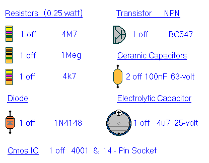
The components used in the circuit should be widely available. However, none of them are critical. So - if you can't find the specified parts -
You're certain to find something that will do just as well.
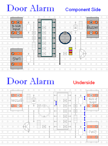
Stripboard or Veroboard is a board drilled with a matrix of 1mm holes - spaced approximately 2.5 mm apart - and joined in rows by copper strips. The piece used has 11 rows with 21 holes in each - and it measures roughly 5 cm by 2.5 cm (2" by 1"). The drawing shows the board with PCB mounting terminal blocks. But to save money - and/or space - the wires may be soldered to veropins - or directly to the board itself.
Parts List
Click Here For A Photograph Of The Prototype.
Construction Notes
Click here if you're new to constructing stripboard projects.
The terminals are a good set of reference points. To fit them - you may need to enlarge the holes slightly. Then turn the board over - and use a felt-tip pen to mark the 10 places where the tracks are to be cut. Use the "actual size" drawing to check that your pattern is
Correctly Marked .
Actual Size
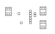
When you're satisfied that the pattern is right - cut the tracks. Make sure that the copper is cut all the way through. Sometimes a small strand of copper remains at the side of the cut and this will cause malfunction. Use a magnifying glass - and backlight the board. It only takes the smallest strand of copper to cause a problem. If you don't have the proper track-cutting tool - a 6 to 8mm drill-bit will do. Just use the drill-bit as a hand tool - there's no need for a drilling machine.
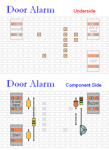
Next fit the nine components and the two links. For clarity, I've split them into three groups - but you can fit them in any order you like. I use a small piece of "Blu Tack" to help hold the components and links in place temporarily - while I solder them to the board. A little putty or modelling clay should work equally as well.
The resistors are all shown lying flat on the board. However, R2 and R3 are mounted standing upright. For the two links - use the off-cuts of wire you've trimmed from the resistors.
Next, examine the board very carefully - to make sure that there are no unwanted solder bridges or other connections between the tracks. If you backlight the board during the examination - it makes potential problem areas easier to spot. When you're satisfied that everything is in order - add the 7 solder bridges to the underside of the board.
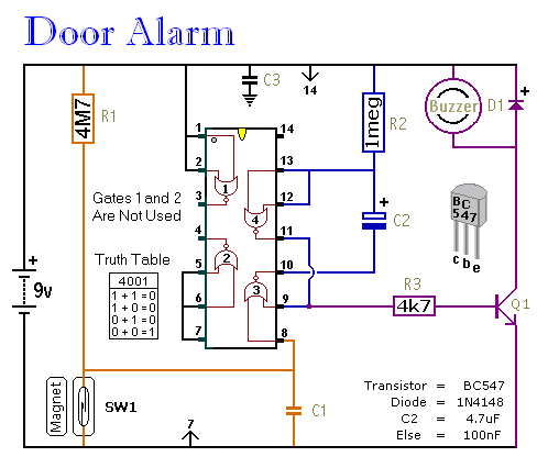
Then double check the position and orientation of all the components. Make sure that the positive side of C2 is connected to Pin 12 - and that the cathode of D1 (the side with the bar) is connected to Pin 14.
Finally, insert the 4001 into the socket. Make sure that pin 1 is in the top left-hand corner - and check carefully that all of the pins are correctly inserted into the socket. Sometimes - instead of entering the socket - a pin will curl up underneath the IC.
You Are Now Ready To Test Your Alarm