How to convert a stripboard layout into a printed circuit board.
A More Complex Project
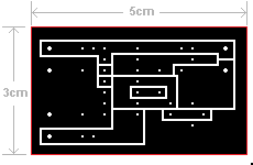
I've used my simple Door Alarm Circuit to illustrate the conversion process. But the technique can be applied to any stripboard layout. The red box is
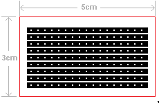
not the edge of the board. It's just there to help confirm that the printout is the right size. The drawings must be printed at a resolution of 100 dots per inch.
Begin by saving a copy of the Stripboard Template. All the work on the template is done from the component side. The resulting drawing will be flipped horizontally before use. Open the template with Paint. Mark off the section of stripboard you need - and delete the rest. How far you take the process after that - depends on the degree of refinement you want.
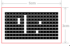
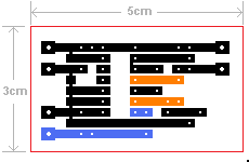
You could simply print the section of board - with all the tracks intact. Or you could take the opportunity to sever the tracks - where required. This can be done - quite conveniently - using the square "Eraser" tool. If you make a mistake - go to "Edit" - and click "Undo".
Unused sections of track can be easily removed - using the rectangular "Select" tool - followed by the "Delete" key. If you make a mistake - go to "Edit" - and click "Undo". The solder bridges can be added using the "Line" tool. I made them wider by choosing one of the broader line options. And I coloured them red - to make them more clearly visible.
The broad line will also blank out the unused holes. If you hold down the "Shift" key as you draw - the line will be straight. You can check your work by calculating the total number of component leads, wire links and terminals the board has to accommodate. In this case - it's 41. When I'd finished removing the unused holes - 41 holes remained. So I was fairly certain that everything was in order.
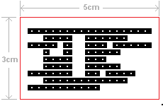
Finally - I used the "Pencil" tool to make the terminal holes larger - and to increase the area of the solder pads. You only have to draw one pad. Then "Copy" it - and use "Paste" to create all the rest.
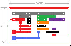
Replacing Wire Links
Each link joins a pair of tracks. Use the "Fill" tool to make each pair of tracks the same colour. Then look for suitable routes to link the pairs together. By re-routing the connection to the transistor's emitter terminal - I was able to clear the way for the blue link.
Replacing the two wire links made a further four holes redundant. It also made some areas of track redundant. For example - the blue track next to pin 8 of the IC - is no longer required. I removed the unwanted portions of track with the "Eraser" tool. Then I used the "Fill" tool to make the tracks black again.
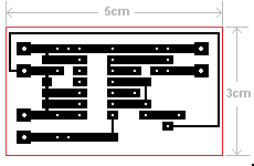
At this stage - you have the opportunity to make improvements to the layout. For example - it's no longer necessary to stretch the transistor's collector lead - as far as the negative Buzzer terminal. There's enough free space to move the connection to its more natural position.
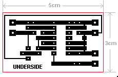
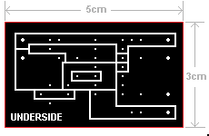
When you're satisfied with your work - flip the drawing horizontally. Click on "Image"- then "Flip/Rotate" and "Ok". At this stage - it's worthwhile adding a word such as "Underside" - to avoid any future confusion.
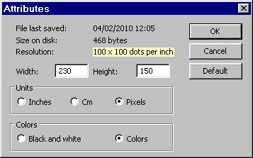
Before you actually make your print - check that the resolution hasn't changed. Click on "Image" - and then "Attributes". The resolution should read "100 x 100 dots per inch". If it has changed - it can be restored to 100 dpi using by one of the techniques described at the bottom of the Stripboard Template Page.
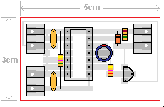
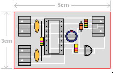
Component Overlay
To check your work - make a copy of the board with pale grey tracks - and add the components to the drawing. You can do this by hand - with pencil and paper. Or you can do it with Paint - as a prelude to producing a component overlay.
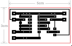
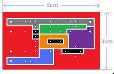
Reduce The Area To Be Etched
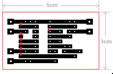
There is no point in removing more copper than you have to. With a simple circuit like this one - the strips can easily be converted into large pads. Use the "Fill" tool to make the various groups of tracks - different colours. Then use the "Line" tool and the "Fill" tool to expand the various groups into pads. There's no single correct pattern. You can make the pads any shape you like.
When you're satisfied with your work - flip the drawing horizontally. Click on "Image"- then "Flip/Rotate" and "Ok". At this stage - it's worthwhile adding a word such as "Underside" - to avoid any future confusion.
Before you actually make your print - check that the resolution hasn't changed. Click on "Image" - and then "Attributes". The resolution should read "100 x 100 dots per inch". If it has changed - it can be restored to 100 dpi using by one of the techniques described at the bottom of the Stripboard Template Page.
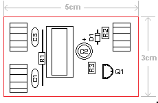
Component Overlay
To check your work - make a copy of the board with pale grey pads - and add the components to the drawing. You can do this by hand - with pencil and paper. Or you can do it with Paint - as a prelude to producing a component overlay.
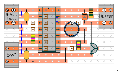
Door Alarm Circuit
 SUGGESTIONS