| All the information you need to build a simple keypad code-operated switch - using cheap off-the-shelf components. |
|---|
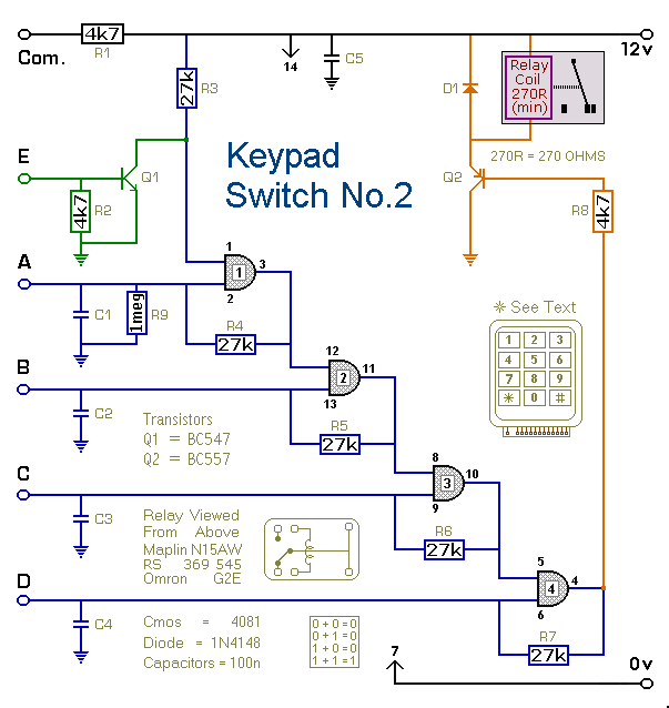
Detailed Circuit Description
This is a simplified version of the Universal Keypad-Operated Switch . I have modified the design to reduce the complexity of the circuit - and the number of components required. As a result - the code is somewhat less secure. However, there should be lots of situations where it will still be adequate.
The circuit is drawn with a 12-volt supply - but it will work at anything from 5 to 15-volts. All you have to do is choose a relay suitable for the supply voltage you want to use. Replace the SPCO/SPDT relay with a multi-pole relay - if it suits your application.
Schematic Diagram
Click Here For A Photograph Of The Prototype.
 Do not use the "on-board" relay to switch mains voltage. The board's layout does not offer sufficient isolation between the relay contacts and the low-voltage components. If you want to switch mains voltage - mount a suitably rated relay somewhere safe - Away From The Board.
Notes
Choose the four keys you want to use as your Code - and connect them to "A B C & D". Wire the common to R1 and all the remaining keys to "E". The circuit will power-up with the relay energized. To de-energize it - you must enter your code. To re-energize it - press any of the keys connected to "E".
To reverse the operation of the circuit replace Q2 with a BC547. With an NPN transistor in this position - the circuit will power-up with the relay de-energized. To energize it - you must enter your code. To de-energize it again - press any of the keys connected to "E".
Any keys not wired to "A B C & D" are connected to the base of Q1. Whenever one of these "Wrong" keys is pressed - Q1 takes pin 1 low and the code entry sequence fails. If you make a mistake while entering the code - simply start again.
The Keypad must be the kind with a common terminal and a separate connection for each key. On a 12-key pad, look for 13 terminals. The matrix type with 7 or 8 terminals will NOT do. A 12-key pad has eight "Wrong" keys connected to "E". If you need a more secure code - use a bigger keypad with more "Wrong" keys.
The Support Material for this circuit includes a step-by-step guide to the construction of the circuit board, a parts list, a detailed circuit description and more.
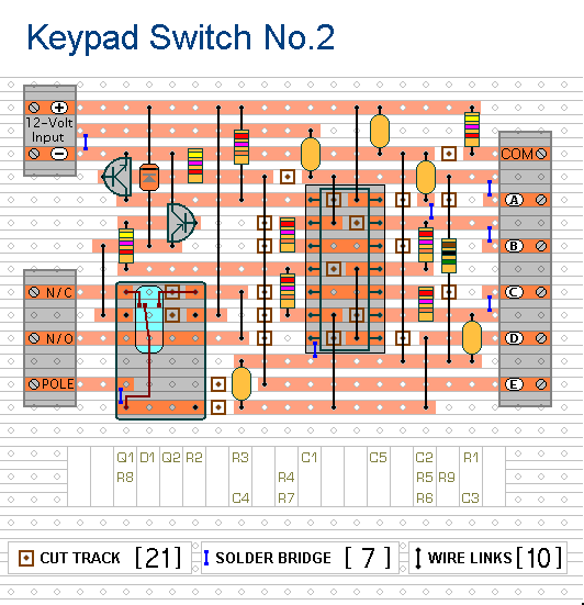
Veroboard Layout
Click Here For A Photograph Of The Prototype.
Keypad Switch No.2 - Support Material
 SUGGESTIONS
