| This simple alarm uses a single Cmos 4060 - and features Exit, Entry and Siren Cut-Off timers. |
|---|
Detailed Circuit Description
This is a single zone alarm - with automatic exit, entry and siren cut-off timers. It will accommodate all the usual types of normally-closed input devices - such as magnetic-reed contacts - foil tape - PIRs etc. But it's easy to add a normally-open trigger.
When the alarm is activated - the siren will sound for a fixed length of time. Then it will switch off - and remain off. The alarm will not re-activate.
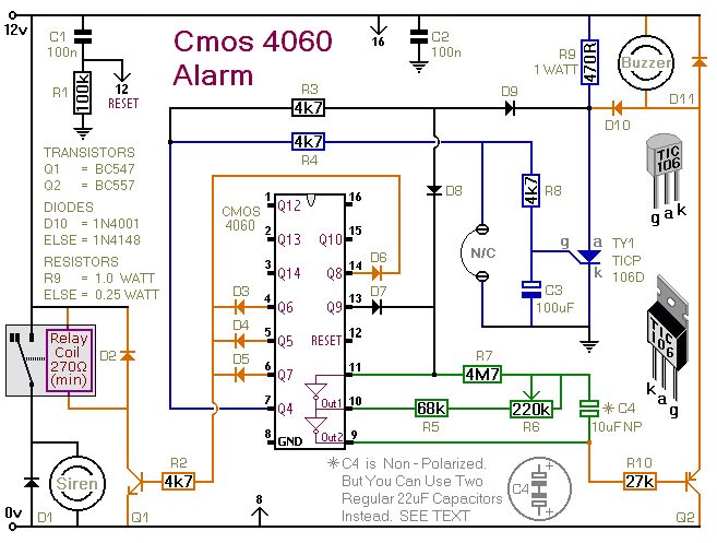
I've used a 12-volt supply in the drawing - but the circuit will work at anything from 5 to 15-volts. All you need do is select a siren, buzzer, and relay to suit the voltage you're using.
Schematic Diagram
Click Here For A Photograph Of The Prototype.
When you switch the alarm on - the buzzer will sound eight times. This is the exit delay. Before the end of the eighth beep - you can leave the building without activating the alarm.
R6 controls the length and speed of the beeps. It can be adjusted to give an exit delay of anything from about ten seconds - up to about a minute. After the eighth beep - the buzzer should stop sounding. This confirms that the loop has been restored within the time allowed.
If the buzzer does not stop - but changes instead to a continuous beep - the loop is open and the building isn't secure. When this happens - you should switch off the alarm - and check for open doors, windows etc.
When you return and open the door - the buzzer will sound again - and the entry delay will start. The entry delay is the same length as the exit delay. But to distinguish it from the exit delay - the buzzer will sound continuously.
If the buzzer is sounding continuously - the alarm has been activated - and the entry delay has begun. If you don't switch the alarm off before the entry delay expires - the siren will sound.
The siren will sound only once. Just as R6 sets the lengths of the exit and entry delays - it also sets the siren cut-off time. The siren cut-off delay is 30 times the length of the exit delay. With the exit delay set at 30-seconds - the siren will sound for about 15-minutes. Then it will switch off - and remain off.
Of course - you can stop the noise at any time by switching off the alarm.
After the cut-off timer has switched the siren off - the buzzer will continue to sound. So when you return - if the buzzer is sounding - you'll know that the alarm has been activated.
Note that D10 is optional. Its job is to sound the buzzer constantly during the entry delay. It's also responsible for keeping the buzzer going after the siren has stopped.
If you leave out D10 - the buzzer will beep eight times during both the exit and entry delays. And - when the siren cuts-off - the buzzer will cut off also.
Alternative Capacitor
A regular electrolytic capacitor is polarised. If the charge on its plates is the wrong way round - DC current will flow through the capacitor. If the current is high enough - the capacitor will heat up and explode. The presence of R5 in the circuit means that this is not going to happen. But if you use a polarised capacitor - it may mean that the oscillator won't run - or won't run reliably.
While the oscillator is running - the polarity of the charge on C4 keeps reversing. So C4 needs to be non-polarised. However - you can simulate a non-polarised 10uF capacitor by connecting two 22uF polarised capacitors back to back - as shown. How and why this works is explained in the Detailed Circuit Description. Because non-polarised capacitors aren't widely available - the prototype was built using two polarised capacitors.
The Support Material for this alarm includes a detailed circuit description - a parts list - a step-by-step guide to construction - and more.
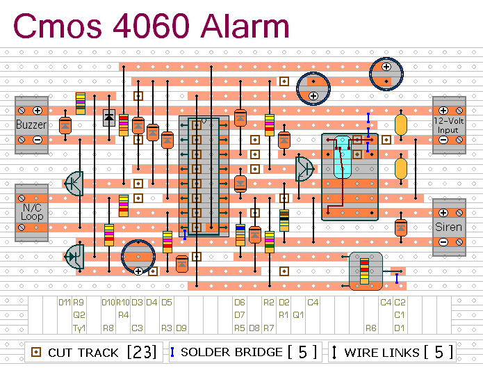
Stripboard Layout
Click Here For A Photograph Of The Prototype.
 SUGGESTIONS
