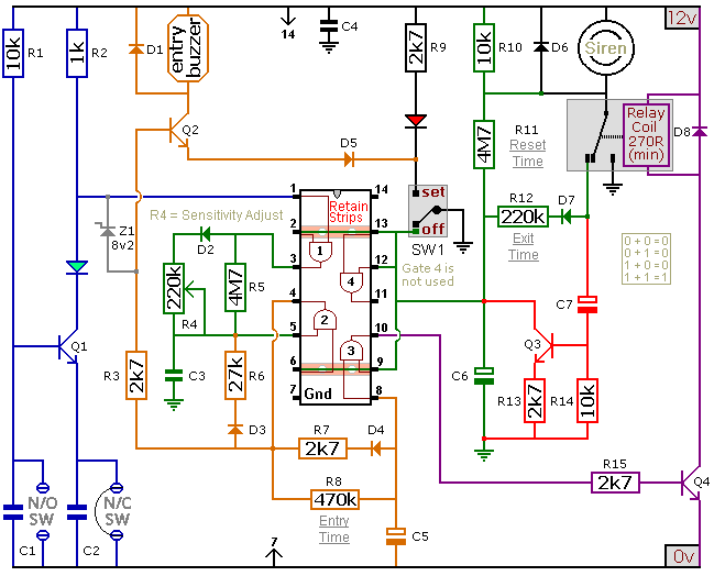
Build this DIY Burglar Alarm System using cheap off-the-shelf components. It has automatic Exit and Entry delays, a timed Bell Cut-off. Use it in your home - small business premises - lock-up etc. It has provision for normally-open and normally-closed switches and will accommodate the usual input devices (Pressure Mats, Magnetic-Reed contacts, Foil Tape, Movement Detectors and Inertia Sensors).
How Inertia Sensors Work
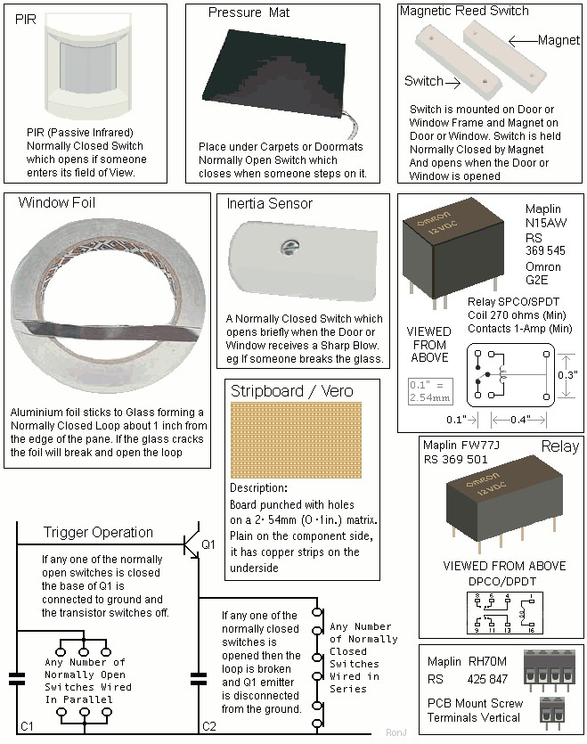
Inertia Sensors are devices that react to vibrations. They do not react to constant low level vibrations of the sort you would get from loud music or heavy road traffic. Instead - they have a certain amount of inertia that must be overcome before they react. In other words - they need a sharp blow - such as that required to break a pane of glass.
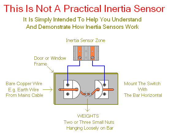
Essentially, they are small normally closed switches - the contacts of which are joined by a specially weighted bar. It's the weights on the bar that provides the inertia. When a blow is struck - the bar bounces - and the switch opens briefly. The length of time the switch is open - i.e. how high the bar bounces - depends on the weight of the bar and the strength of the blow.
The alarm circuit sensitivity is adjusted by altering the speed at which it reacts - i.e. the speed at which C3 charges through R4. At its most sensitive - the value of R4 is zero. So C3 will charge very quickly. The alarm will react to a very short opening of the circuit - so a light tap on the sensor is all that's required.
Because a large number of small insignificant impulses might build up the charge on C3 to the point where it would cause a false alarm - R5 is included to keep C3 discharged in standby mode.
Power Supply
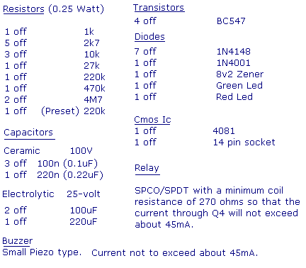
In standby mode - the circuit should not use more than a few milliamps. It's only when the relay is energised and the siren is sounding that any real current is required. The actual current consumption depends on the sounder you use. A conventional bell uses up to about 400ma. An electronic siren generally uses less. In any case - a 1-amp power supply should be sufficient. The
Alarm Power Supply is ideal.
Parts List
|
|---|
|
|
|---|
Construction
Click here if you're new to constructing stripboard projects.
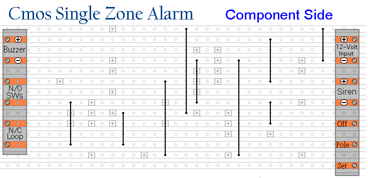
The terminals are a good set of reference points. To fit them, you may need to enlarge the holes slightly. Then turn the board over and use a felt-tip pen to mark the 34 places where the tracks are to be cut. Before you cut the tracks, use the "actual size" drawing to Check That The Pattern is Correctly Marked .
When you're satisfied that the pattern is right - cut the tracks. Make sure that the copper is cut all the way through. Sometimes a small strand of copper remains at the side of the cut and this will cause malfunction. Use a magnifying glass - and backlight the board. It only takes the smallest strand of copper to cause a problem. If you don't have the proper track-cutting tool - then a 6 to 8mm drill-bit will do. Just use the drill-bit as a hand tool - there's no need for a drilling machine.
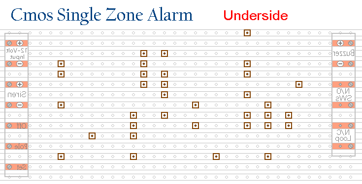
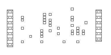
Actual Size Of Pattern
Next make and fit the Nine Wire Links. I used bare copper wire on the component side of the board. Telephone cable is suitable - the single stranded variety used indoors to wire telephone sockets. Stretching the core slightly will straighten it - and also allow the insulation to slip off.
The next stage is to fit the 14 resistors - the preset - most of the diodes - and the IC socket. Using a socket reduces the chances of damaging the IC - and makes it easier to replace if necessary. Pay particular attention to the orientation of the diodes. The resistors and diodes are all shown lying flat on the board. However, those connected between close or adjacent tracks are mounted standing upright. See the Photograph Of The Prototype
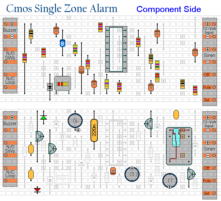
Next - fit the four transistors - the remaining diode - the two LEDs - the seven capacitors - and the relay. Pay particular attention to the orientation of the electrolytic capacitors. They generally have a light coloured stripe down the side next to the negative terminal. Note that C6 and C7 have their positive terminals facing the bottom of the board. See the Photo Of The Prototype
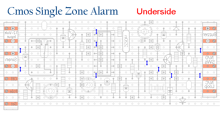
Finally, examine the underside of the board carefully - to make sure that there are no unwanted solder bridges or other connections between the tracks. If you backlight the board during the examination - it makes potential problem areas easier to spot.
When you're satisfied that everything is in order - add the ten solder bridges to the underside of the board. The tracks are cut to accommodate two sizes of preset. If you've used the smaller preset - like the one in The Prototype - you'll need to add an extra solder bridge to connect the wiper to the track above.
Finish off by inserting the Cmos 4081 into the socket. Pin 1 of the IC should be in the top left-hand corner. Check that all 14 pins have entered the socket. Sometimes - instead of entering the socket - a pin will curl up under the IC.
You're Now Ready To Test Your Circuit
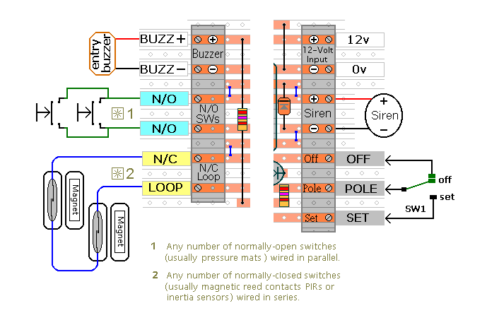
Connections
General Information
Click Here For A Photograph Of The Prototype
 SUGGESTIONS