All the information you need to build a simple keypad-operated electronic door lock - using cheap off-the-shelf components.
This circuit is designed to operate an electrical door-release mechanism - but it will have other applications. Enter the four-digit code of your choice - and the relay will energize for the period of time set by C4 & R4. Use the relay contacts to power the release mechanism. The standby current is virtually zero - so battery power is a realistic option.
The circuit is drawn with a 12-volt supply - but it will work at anything from 5 to 15-volts. All you have to do is choose a relay suitable for the supply voltage you want to use. Replace the SPCO/SPDT relay with a multi-pole relay - if it suits your application.
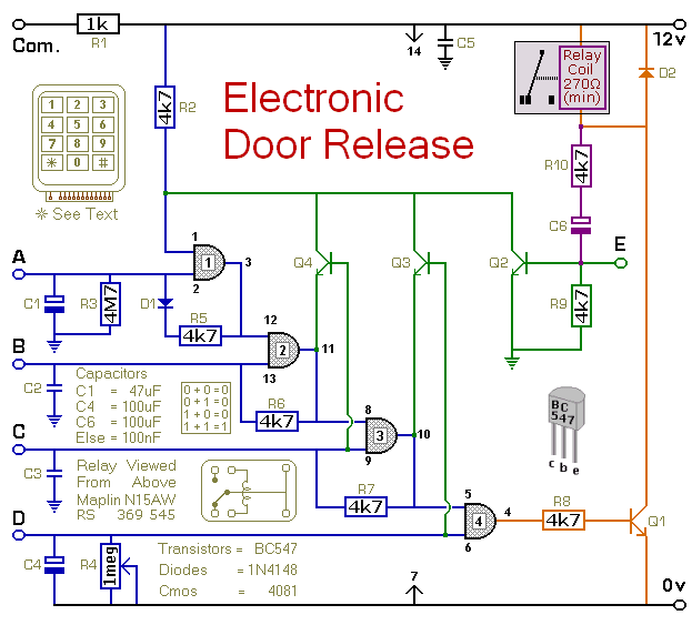
Schematic Diagram
Click Here For A Photograph Of The Prototype
 Do not use the "on-board" relay to switch mains voltage. The board's layout does not offer sufficient isolation between the relay contacts and the low-voltage components. If you want to switch mains voltage - mount a suitably rated relay somewhere safe - Away From The Board.
Notes
Choose the four keys you want to use as your code - and connect them to "A B C & D". Wire the common to R1 and all the remaining keys to "E". When you press your four keys - in the right order - the relay will energize.
With the values of C4 & R4 as shown - and with R4 set to its maximum - the relay will de-energized about one minute after "D" is released. However - if you replace C4 with a 100nF capacitor - and replace R4 with a 4k7 fixed resistor - the relay will de-energize the moment "D" is released.
Any keys not wired to "A B C & D" are connected to the base of Q2. Whenever one of these "Wrong" keys is pressed - Q2 takes pin 1 low and the code entry fails. Similarly, if "C" or "D" is pressed out of sequence - Q4 or Q3 will take pin 1 low and the code entry will fail. If you make a mistake while entering the code - simply start again.
The Keypad must be the kind with a common terminal and a separate connection for each key. On a 12-key pad, look for 13 terminals. The matrix type with 7 or 8 terminals will NOT do. A 12-key pad has eight "Wrong" keys connected to "E". If you need a more secure code - use a bigger keypad with more "Wrong" keys.
The Support Material for this circuit includes a step-by-step guide to the construction of the circuit board, a parts list, a detailed circuit description and more.
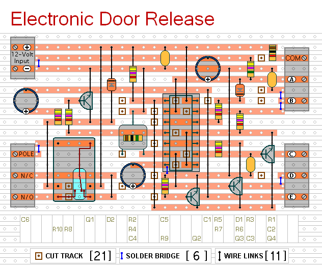
Veroboard Layout
Click Here For A Photograph Of The Prototype
 SUGGESTIONS
