This is a simple - easy to build - fridge-type alarm circuit. For power - I used a small 9-volt battery. But the circuit will work from 5 to 15-volts - just choose a buzzer that's suitable for the voltage you're using. The standby current is virtually zero - so the battery life is good.
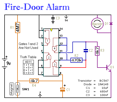
Schematic Diagram
Click Here For A Photograph Of The Prototype.
Notes
It's very important that fire-doors are kept closed at all times. If they're left propped open - they're no longer doing their job. If SW1 is connected to the fire-door - the alarm circuit will allow you to open and close the door without sounding the Buzzer. However - if the door is left open for more than about 30 seconds or so - the Buzzer will start to give a series of short warning beeps.
The length of the initial delay is fixed by R1 and C1. The length and speed of the beeps is set by R2 and C2. With the values shown in the diagram - after an initial delay of about 30 seconds - the Buzzer will switch on and off at about half-second intervals.
I've drawn SW1 as a magnetic reed-switch - but you can use any type of switch that suits your application. If you have more than one fire-door to protect - you can use more than one switch. Just wire all of your switches in series.
Changing the Output Time
Roughly speaking - the length of the initial delay is proportional to the values of R1 and C1. In other words - if you double the value of either R1 or C1 - you will double the length of the initial delay. If you halve the value of either R1 or C1 - you will halve the length of the initial delay.
The same applies to the length of the beep. Roughly speaking - the length of the beep is proportional to the values of R2 and C2. In other words, if you double the value of either R2 or C2 - you will double the length of the beep. If you halve the value of either R2 or C2 - you will halve the length of the beep.
If you want an accurate output time - use a variable-resistor (or preset) in place of R2. Then simply adjust the resistor until you get the length of beep you require.
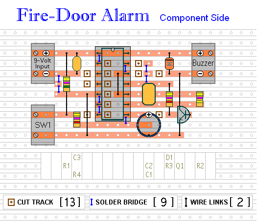
Veroboard Layout
Click Here For A Photograph Of The Prototype.
The
Support Material for this circuit includes a parts list - a detailed circuit description - a step-by-step guide to construction and details of
How To Test Your Finished Alarm.
If you're new to using Cmos ICs - and you'd like to know more about how they work - take a look at my introduction to
The Cmos 4011. It makes use of the present Fire-Door Alarm Circuit to explain in detail, just how the IC operates.
Fire-Door Alarm - Circuit Simulation


