All the information you need to build a simple keypad operated switch. Although it's designed to operate the Modular Burglar Alarm - it will have other uses.
When you enter the first four digits of your five-digit security code - the relay will energize. Entering the full five-digit code - will de-energize the relay. The circuit was designed to control the Modular Burglar Alarm System - but it will have other applications. A simpler - Four-Digit Version - of the circuit is also available.
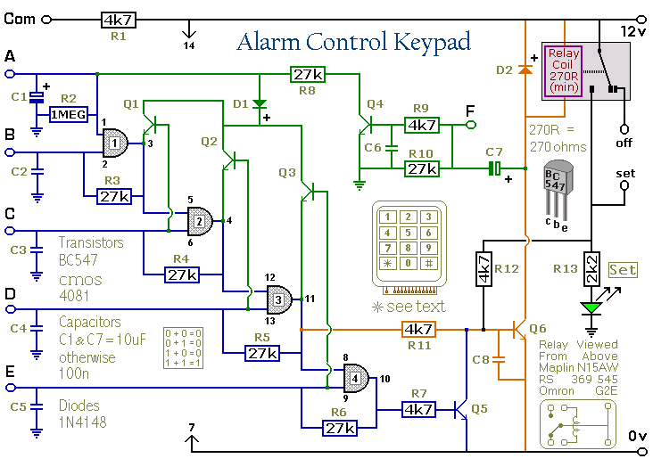
Schematic Diagram

Notes
Choose the five-digit security code you want to use - and connect the corresponding keypad keys to "A B C D & E". Wire the keypad's common terminal to R1 - and all the remaining keypad keys to "F".
The circuit is easy to use. When you enter the first four digits of your security code - the relay energizes. The 12-volt output moves from the "off" to the "set" terminal - and the green LED lights.
When you enter the full five-digit code - the relay de-energizes. The 12-volt output moves from the "set" to the "off" terminal - and the green LED is extinguished.
Any keys not wired to "A B C D & E" are connected to "F". Whenever one of these "Wrong" keys is pressed - the code entry fails. And the code entry sequence resets. Pressing the "Right" keys - in the wrong order - will also reset the circuit. If you make a mistake while entering the code - simply start again.
The Keypad must be the kind with one common terminal - and a separate connection for each key. On a 12-key pad - look for 13 terminals. The matrix type with 7 or 8 terminals will NOT do.
The Support Material includes - a detailed circuit description - a parts list - a step-by-step guide to the construction of the circuit board - and plans for a DIY keypad.
With a 12-key pad - almost 100 000 different five-digit codes are available. If you need a more secure code - you could simply use a bigger keypad with more "Wrong" keys wired to "F". A 16-key pad will provide over half a million different five-digit codes.
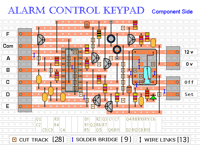
Veroboard Layout

 SUGGESTIONS
 SUGGESTIONS

