These two circuits allow you to choose the light level at which the relay will energize.
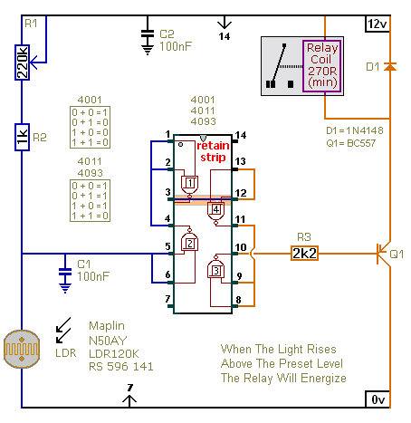
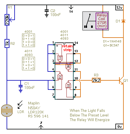
The first circuit energizes the relay when the light rises above the preset level. The second circuit energizes the relay when the light falls below the preset level. The two circuits are practically identical. The only difference between them is the polarity of the transistor. The type of LDR is not critical. The important thing is the voltage on pins 5 & 6. Any type of LDR should work satisfactorily. But you may need to change the value of R1 - to achieve the desired range of adjustment.
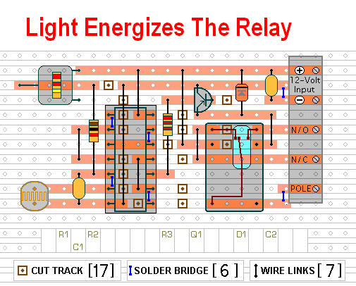
Circuit No.1
 Do not use the "on-board" relay to switch mains voltage. The board's layout does not offer sufficient isolation between the relay contacts and the low-voltage components. If you want to switch mains voltage - mount a suitably rated relay somewhere safe - Away From The Board. I've used a SPCO/SPDT relay - but you can use a multi-pole relay if it suits your application.
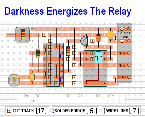
Circuit No.2
The circuits are designed for a 12-volt power supply. However - they will both work at anything from 5 to 15-volts. All you need do is select a relay with a coil voltage that suits your supply. And make sure that the coil doesn't draw more than about 50mA - otherwise the transistor might be overloaded. I've used a single-pole relay in the diagrams - but you can use a multi-pole relay if it suits your application.
Although all three Cmos ICs will work - the 4093 is the best choice. Light levels change slowly - and the outputs of the 4001 & 4011 can take a few seconds to change state. During this time - the relay may rattle or buzz. The 4093 switches its outputs very quickly - and this will reduce or eliminate the noise.
The Support Material for this circuit includes a parts list - a step-by-step guide to the construction of the circuit-board - a detailed circuit description - and more.
 SUGGESTIONS