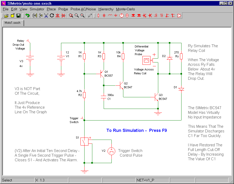
The circuit uses a small single pole relay - such as the 12v Omron G2E. The coils of these low voltage DC relays behave just like resistors. I've used a 270 ohm resistor (Ry) to simulate my relay coil. The Differential Voltage Probe measures the voltage across the relay coil. And the state of the relay is determined by the level of that voltage.
You'll see from the graph below that - on activation - the voltage across the coil rises sharply to 12v. This causes the relay to energize - and the siren will sound. Over the following few minutes - the coil voltage falls back to zero. On its way - when it passes below about 4v - the relay will de-energize - and the siren will be silenced. The graph shows that this will occur about 110 seconds into the simulation. I produced the blue line artificially - using V3 - a separate 4v DC Supply.
Graphs
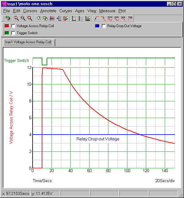
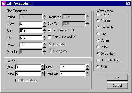
The green line represents the trigger pulse. It's produced by S1 and V2. In standby mode V2 is always 0v. But ten seconds into the simulation - it rises to 5 volts - for five seconds. This switches S1 on. And S1 connects R2 to ground. In other words - when V2 rises to 5 volts - it closes the trigger switch - turns Q1 on - charges C1 - and activates the alarm.
The Trigger Pulse Settings (V2)
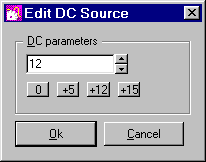
Power Supply Setting
The default power source is 5vdc. If you ever need to change that value - select the power source symbol (e.g. V1 in the schematic) - and press F7. Then change the contents of the "Parameters" window - by typing in your new value. Alternatively - you can simply use one of the preset buttons provided.
Analysis Settings
The analysis is fairly straight forward. The "Mode" should be set to "Transient". And the "Stop Time" should be long enough to allow the alarm to complete one "activation and reset" cycle. I chose 150 seconds.
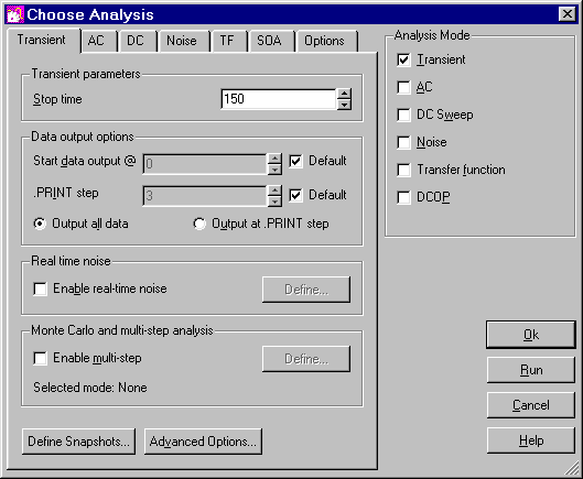
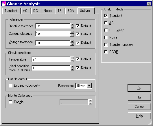
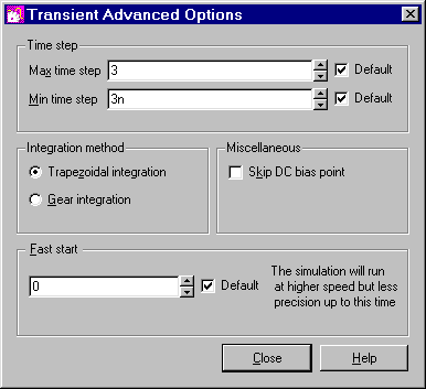
All the remaining settings are "Default". There will be times when you'll find it necessary or advantageous to change the "Tolerances" - the "Integration Method" - the "Time Step" etc. But for this circuit - the default settings are all adequate.
The Value Of C1
In order to produce a reset time of about 2 minutes - I've had to cheat a little. I've had to increase the 47uF capacitor to 390uF. The reason is simple. The base-emitter junctions - of the simulated Q2 & Q3 - are discharging C1 far too quickly. This problem can be traced to the extremely low input impedance of the BC547 model - used in the simulation. And it arises because there isn't a satisfactory "one-size fits-all" model for the BC547 - or for any other transistor.
The input impedance of a transistor is - in effect - the apparent resistance between the base and emitter pins. I say "apparent" resistance - because there isn't an actual resistor within the base-emitter junction. The junction just behaves like a resistor. That is - it restricts the flow of current.
The value of the apparent resistor - the impedance of the base-emitter junction - is influenced by a number of things. One is the gain of the transistor - and another is the size of the current flowing through its emitter. If the gain is very high - and the current in the emitter is very small - the transistor's input impedance will be high.
In our circuit - Q2 & Q3 are connected together to form a slightly modified version of a Darlington-Pair. This means that their overall gain is very high. Added to that - the Q2 emitter current is extremely small. This combination of high gain - and low emitter current - makes the input impedance of the two transistors - very high. It's far higher than that provided by the transistor models. In other words - in the real world - with real transistors - C1 will discharge much more slowly.
The simplest solution is to do what I did - inflate the value of C1. But there's no reason why you shouldn't choose to use a more appropriate transistor model instead. Included in the
Download Material is a file called "MyMods.lb" It contains a transistor model I've called "BC547my". It's exactly the same as the original BC547 - except that I've increased to 10 ohms - the value of the transistor's "apparent" emitter resistance (RE). This new model reflects more accurately - the effect of the low emitter current. If you use this replacement model - you can restore C1 to its original value.
The
Download Material includes several versions of the simulation. See the "Readme.txt". Some use my modified transistor model - and the corresponding 47uF capacitor. To run these simulations successfully - you'll need to install the new transistor model. This is very easy. Simply drag and drop the "MyMods.lb" file into the small "SIMetrix Command Shell" window. And - when asked - confirm that you want to install the new model. Don't Worry! You're not overwriting anything. All the existing models are still there.