The components used in the circuit should be widely available. However, none of them are critical. So - if you can't find the specified parts -
You're certain to find something that will do just as well.
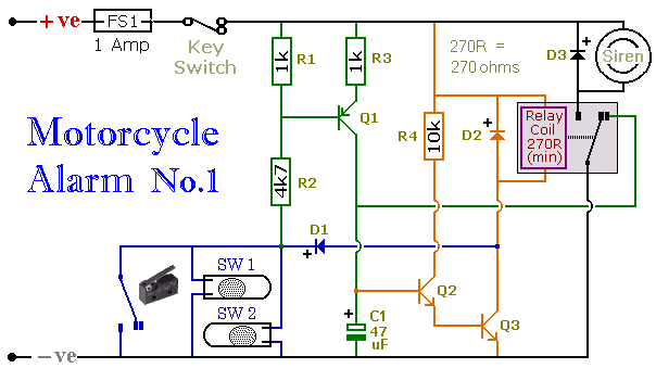
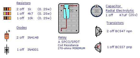
There is nothing special about the transistors. So long as the pnp/npn requirement is satisfied - any small transistors with a gain (hfe) greater than 100 and an Ic(max) of at least 100mA should do. But remember that the pin configuration of your transistors may be different from that of the BC547 and BC557.
I designed the alarm with a 12-volt supply in mind. So the circuit uses a 12-volt relay - and a 12-volt siren. But it will also work with a 6-volt supply. To protect your "Classic" machine - just choose a relay and a siren suitable for the lower voltage.
I didn't want the circuit to drain the motorcycle battery - so I designed it to have a very low standby current. This was achieved by using normally-open trigger-switches - by avoiding purely resistive connections between the positive rail and ground - and by ensuring that every transistor is turned firmly off. In standby mode - the current is virtually zero.
The low standby current means that the alarm may be powered by dry-batteries. This would make it more secure - because it could not be defeated by disconnecting the motorcycle battery. It also means that the alarm may be used in situations where a power source is not available. For example, it could be fitted inside a computer - to sound the alarm if a thief tries to pick it up and carry it away.
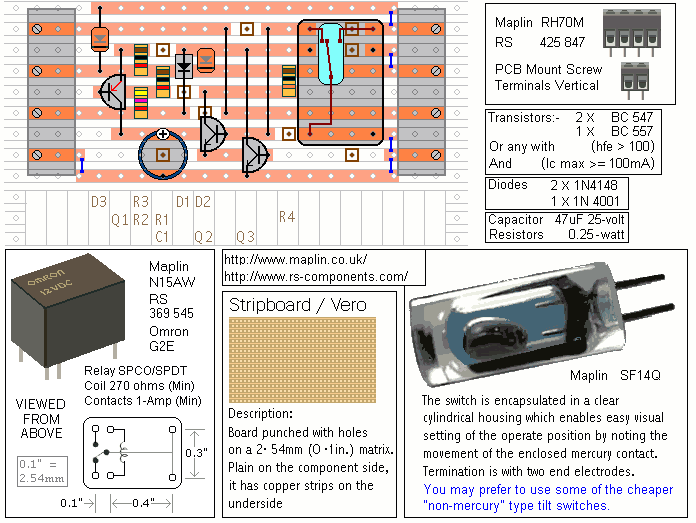
Stripboard or Veroboard is a board drilled with a matrix of 1mm holes spaced approximately 2.5 mm apart and joined in rows by copper strips. The piece required has 9 rows with about 20 holes in each - and measures roughly 5 cm by 2.5 cm (2" by 1"). The drawing shows the board with PCB mounting terminal blocks but - to save money and/or space - the wires may be soldered to veropins or directly to the board itself.
The fuse
MUST be fitted as close to the power source as possible. This is
VERY IMPORTANT! The fuse is there to protect the wiring - not the circuit board. Exactly how and where the alarm is fitted will depend on the make of your motorcycle. The only advice I can give is that the switches - circuit board and siren should be made as inaccessible as possible.
As a rule - the volume of a siren is related to the current it draws. The more current - the louder the noise. A typical siren will take up to about 300mA.
I don't advise using the bike's own horn in place of the siren. The horn is generally easily accessible. The thief can simply disconnect it. However, if you choose to use the horn remember that the alarm relay is too small to switch the heavier load. Connect the coil of a suitably rated relay to the Siren output - and use its contacts to sound the horn.
"Mercury Tilt Switches" are generally small glass bulbs with two contacts at one end. Inside the bulb is a "ball" of mercury. When the switch is "tilted" a few degrees off the horizontal - the mercury flows to one end and connects the contacts together.
The mercury switches are fitted so that they close when the steering is moved - or when the bike is lifted off its side-stand - or pushed forward off its centre-stand. The micro-switches (hinge-lever switches) are used to protect removable panels and the lids of panniers (saddlebags) etc.
If the tilt switches are fitted properly - the circuit should reset a minute or two after the bike has been returned to its centre-stand or kick-stand. If it's not returned to one of its stands - and one of the trigger-switches remains closed - the siren will continue to sound indefinitely.
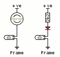
Mercury tilt switches are expensive. You may prefer to use the cheaper "non-mercury" type. The main difficulty with these is that - unlike mercury switches - you can't actually see what's happening inside. This can make them troublesome to position accurately. When setting-up the switching point, you may find it helpful to use a small buzzer - or an LED connected in series with a 2k2 resistor. Alternatively - you could
Add The LED Module to the alarm - and use it to help you position the switches.
Parts List
Construction Notes
Click here if you're new to constructing stripboard projects.
The terminals are a good set of reference points. To fit them - you may need to enlarge the holes slightly. Then turn the board over and use a felt-tip pen to mark the 9 places where the tracks are to be cut. Before you cut the tracks, use the "actual size" drawing to
Check That The Pattern is Correctly Marked .
Actual Size
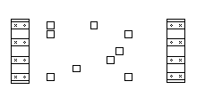
When you're satisfied that the pattern is right - cut the tracks. Make sure that the copper is cut all the way through. Sometimes a small strand of copper remains at the side of the cut and this will cause malfunction. Use a magnifying glass - and backlight the board. It only takes the smallest strand of copper to cause a problem. If you don't have the proper track-cutting tool - a 6 to 8mm drill-bit will do. Just use the drill-bit as a hand tool - there's no need for a drilling machine.
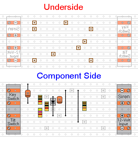
The next stage is to fit the 4 resistors, the 3 diodes and the 2 links. I use a small piece of "Blu Tack" to hold the components and links in place temporarily - while I solder them to the board. A little putty or modelling clay should work equally as well.
The components are all shown lying flat on the board. However, D2 and the four resistors are mounted standing upright. For the two links - use the off-cuts of wire you've trimmed from the resistors. Then fit the transistors, the capacitor and the relay. Note that the PNP transistor (BC557) is the one with the emitter coloured red.
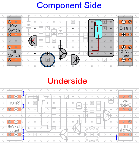
Double check the position and orientation of all of the components. Then examine the underside of the board very carefully - to make sure that there are no unwanted solder bridges or other connections between the tracks. If you backlight the board during the examination - it makes potential problem areas easier to spot. When you're satisfied that everything is in order - add the 5 solder bridges to the underside of the board.
Set Your Alarm Automatically
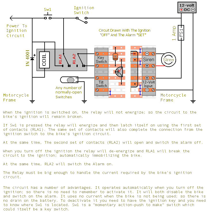
You can use a keyswitch or a hidden switch to operate the alarm. But add a small relay - and the alarm can be made to operate itself automatically. Below are two different circuits. In the first - every time you switch off the ignition - the alarm will turn itself on. And every time you switch on the ignition -, the alarm will turn itself off. The second circuit works in the same way - but with the added security provided by Sw1. The ignition key alone will not turn the alarm off. You need to push Sw1 before the relay will energize.
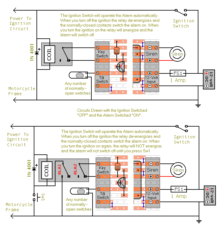
Whichever circuit you use - the relay will only be energized while the ignition is on. When the bike is parked - and the alarm is on - the relay coil is not using any current. So there is no drain on the battery. Depending on the circuit - you'll need a single or double-pole relay with a contact rating of at least 1-amp. When you have it all wired-up correctly - protect it from the elements by wrapping it well with several layers of electrical tape.
Add an Immobilizer to the Machine
Before fitting this or any other immobilizer to your bike, carefully consider both the safety implications of its possible failure - and the legal consequences of installing a device that could cause an accident. If you decide to proceed - you will need to use the highest standards of materials and workmanship.
Remember that the relay must be suitable for the current it's required to carry. Choose one specifically designed for automobiles - it will be protected against the elements and will give the best long-term reliability. You don't want it to let you down on a cold wet night - or worse still - in fast moving traffic!!!
Please note that I am UNABLE to help any further with either the choice of a suitable relay - or with advice on its installation.