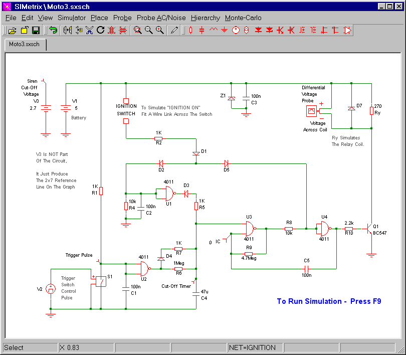
The circuit uses a small single pole relay - such as the 12v Omron G2E. The coils of these low voltage DC relays behave just like resistors. I've used a 270 ohm resistor (Ry) to simulate my relay coil. The Differential Voltage Probe measures the voltage across the relay coil. And the state of the relay is determined by the level of that voltage.
You'll see from the graph below that - on activation - the voltage across the coil rises sharply to 5v. This causes the relay to energize - and the siren will sound. Over the following 30 seconds or so - the coil voltage continues to rise and fall. This causes the relay to energize and de-energize. And the siren will sound intermittently.
Graphs
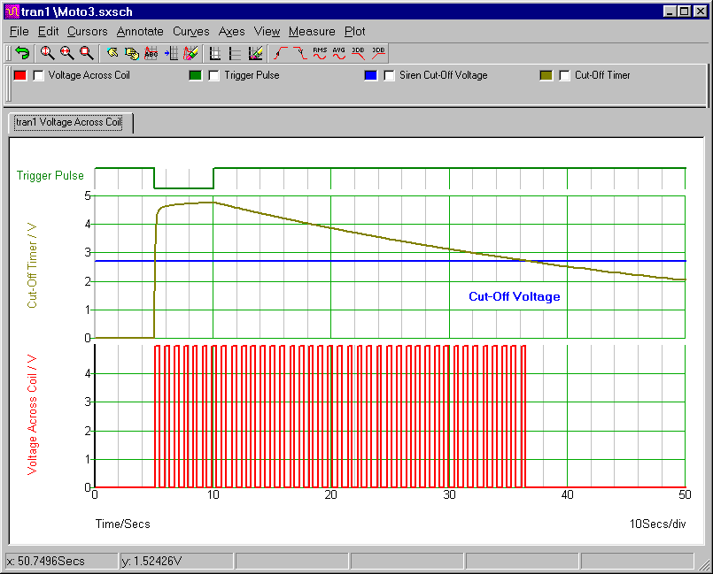
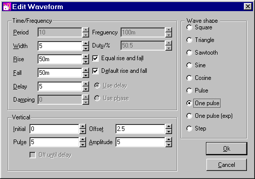
The green line represents the trigger pulse. It's produced by S1 and V2. In standby mode V2 is always 0v. But five seconds into the simulation - it rises to 5 volts - for five seconds. This switches S1 on. S1 connects the inputs of gate 2 to ground. And the output of gate 2 goes high. The high gate 2 output charges C4 - and that's what activates the alarm.
The Trigger Pulse Settings (V2)
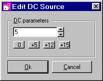
Power Supply Setting
The default power source is 5vdc. If you ever need to change that value - select the power source symbol (e.g. V1 in the schematic) - and press F7. Then change the contents of the "Parameters" window - by typing in your new value. Alternatively - you can simply use one of the preset buttons provided.
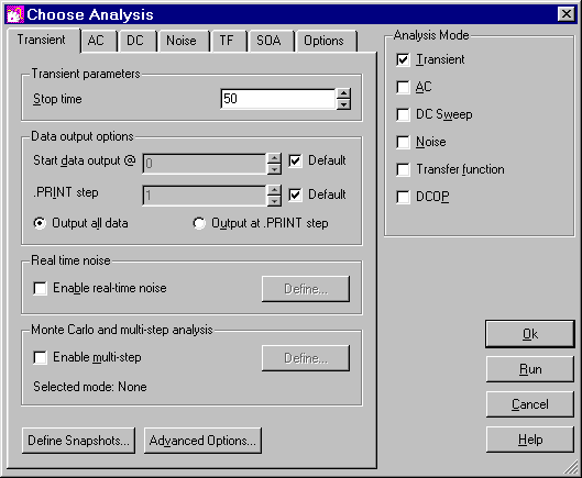
Analysis Settings
The analysis is fairly straight forward. The "Mode" should be set to "Transient". And the "Stop Time" should be long enough to allow the alarm to complete one "activation and reset" cycle. I chose 50 seconds.
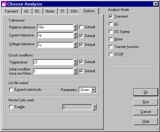
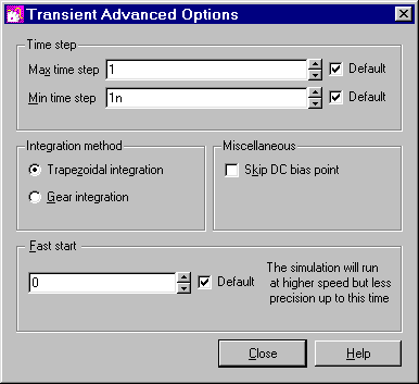
To coax the simulation to run successfully - I had to increase the value of the "Relative Tolerance" figure. You'll find it under the "Options" tab. All the remaining settings are "Default". There will be times when you'll find it necessary or advantageous to change the other "Tolerances" - the "Integration Method" and the "Time Step" etc. But for this circuit - the remaining default settings are adequate.
Why Is The Simulation 5-Volts?
The Cmos Models that come with SIMetrix are designed for a 5-volt supply. So, to keep matters simple, I've set up a 5-volt simulation. However - the alarm itself is designed for a 12-volt supply. So included in the
Download Material - you'll find 12v simulations for both the 4011 and the 4093. To run these extra simulations successfully - you'll need to install my 12v Cmos models. This is very easy. Simply drag and drop the "MyMods.lb" file into the small "SIMetrix Command Shell" window. And - when asked - confirm that you want to install the new model. Don't Worry! You're not overwriting anything. All the existing models are still there.