You can use the free
SIMetrix Circuit Simulator to run
My Simulations. Or you can use my observations, tips and techniques - to help you create a suitable file for a different simulator programme. If you do decide to create your own simulation - it may still be worthwhile to download SIMetrix and run my simulations for comparison.
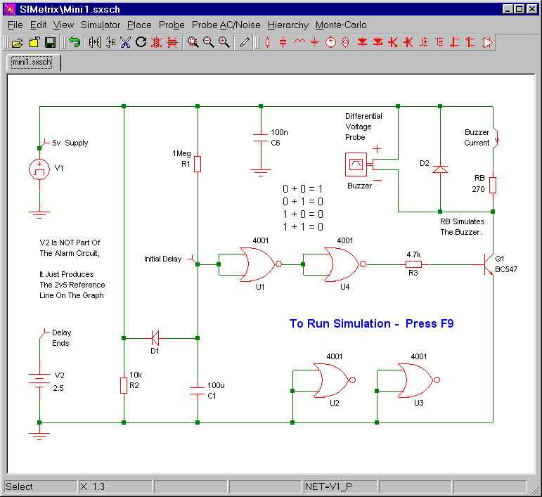
Circuit No.1
This circuit uses a small piezo buzzer. But you can also connect the coil of a small relay to the buzzer terminals. I've used a 270 ohm resistor (RB) to simulate my buzzer and/or relay coil. The differential voltage probe measures the voltage across the resistor. And the state of the buzzer / relay - is determined by the level of that voltage.
Mini-Alarms 1 & 2
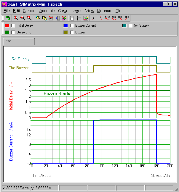
In the graph below - the top line represents the power supply. Twenty seconds into the simulation - SIMetrix switches the power on - and C1 begins to charge through R1. The voltage on pins 1 & 2 - that's the red line - starts to rise. And when it reach about 2v5 - the buzzer sounds.
Circuit No.1 - Graphs
Mini-Alarms 1 & 2
After 180 seconds - SIMetrix switches the power off again. The buzzer stops immediately. The delay timer is also quickly reset - as C1 discharges through D1 & R2. The bottom blue line represents the current that flows through the 270 ohm resistor. It's roughly 18mA.
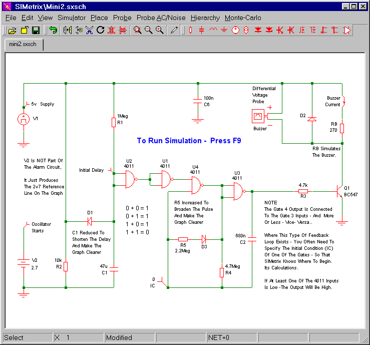
Circuit No.2
This circuit uses a small piezo buzzer. But you can also connect the coil of a small relay to the buzzer terminals. I've used a 270 ohm resistor (RB) to simulate my buzzer and/or relay coil. The differential voltage probe measures the voltage across the resistor. And the state of the buzzer / relay - is determined by the level of that voltage.
Mini-Alarms 1 & 2
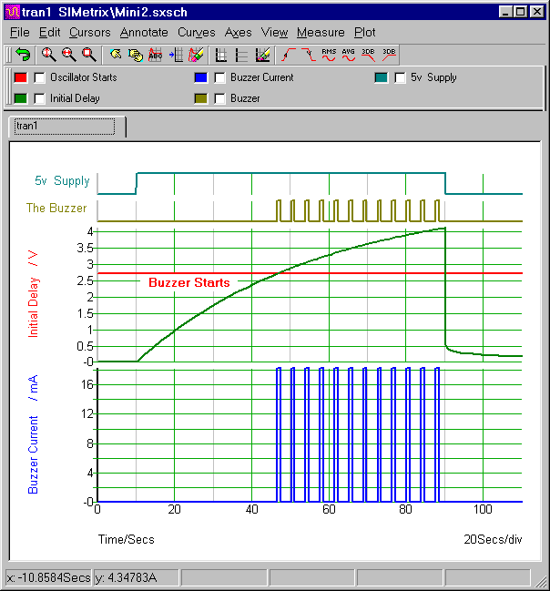
In the graph below - the top line represents the power supply. Ten seconds into the simulation - SIMetrix switches the power on - and C1 begins to charge through R1. The voltage on pins 5 & 6 - that's the green line - starts to rise. And when it reach about 2v7 - the buzzer sounds.
Circuit No.2 - Graphs
Mini-Alarms 1 & 2
After 90 seconds - SIMetrix switches the power off again. The buzzer stops immediately. The delay timer is also quickly reset - as C1 discharges through D1 & R2. The bottom blue line represents the current that flows through the 270 ohm resistor. It's roughly 18mA.
Why Are The Simulations 5-Volts?
The Cmos Models that come with SIMetrix 5.40 are designed for a 5-volt supply. And, to keep matters simple, I've set up a 5-volt simulation. However - the alarm itself is designed to work over a range of supply voltages. So included in the
Download Material - you'll also find 9v and 12v simulations. To run these additional simulations successfully - you'll need to install my 9v & 12v Cmos models. This is very easy. Simply drag and drop the "MyMods.lb" file into the small "SIMetrix Command Shell" window. And - when asked - confirm that you want to install the new models. Don't Worry! You're not overwriting anything. All the existing models are still there.


