This is a selection of small self-contained alarm circuits. The main features of each alarm are described on the circuit diagram itself. They all have a very low standby current. So they are ideal for battery operation. Each pair of circuits will print out on an A4 sheet. Although they are described as alarm circuits - they will have other applications.
Sw1 is drawn as either a micro-switch or a magnetic-reed contact but - so long as it does the job - you can use whatever type of switch you like. Use more than one switch if it suits your application. The output device is a "piezo" buzzer - requiring a current of about 10mA. But - you can replace it with a relay - and use the relay contacts to switch whatever device you like. Just make sure that the relay coil doesn't draw more than about 50mA - otherwise the transistor might be overloaded.
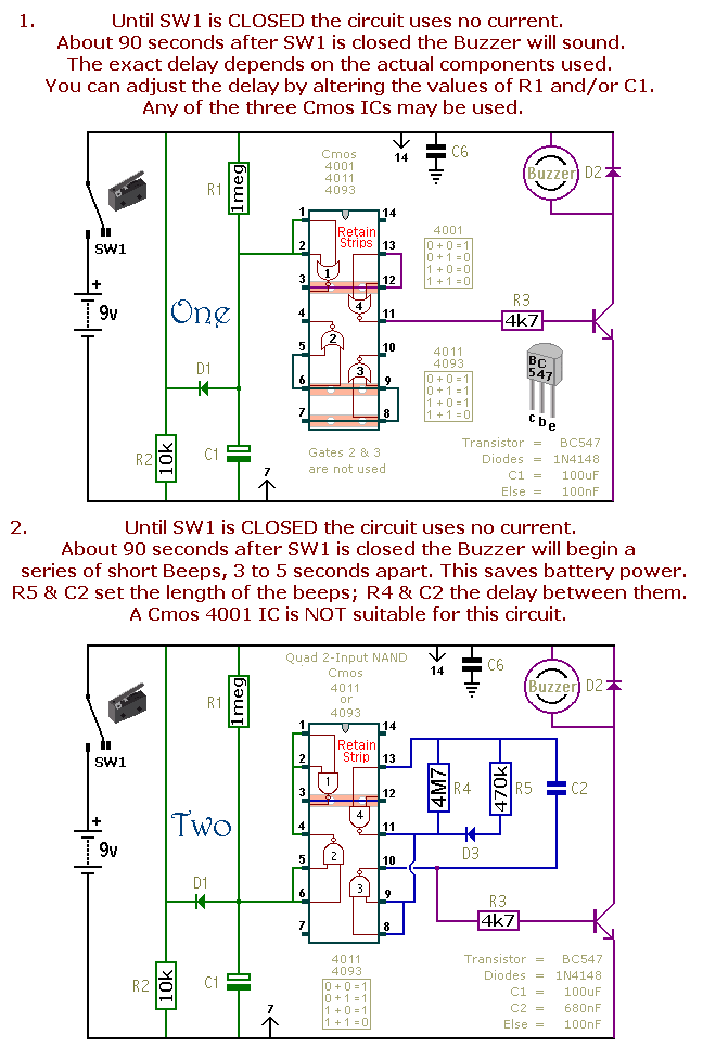
Schematic Diagrams 1 & 2
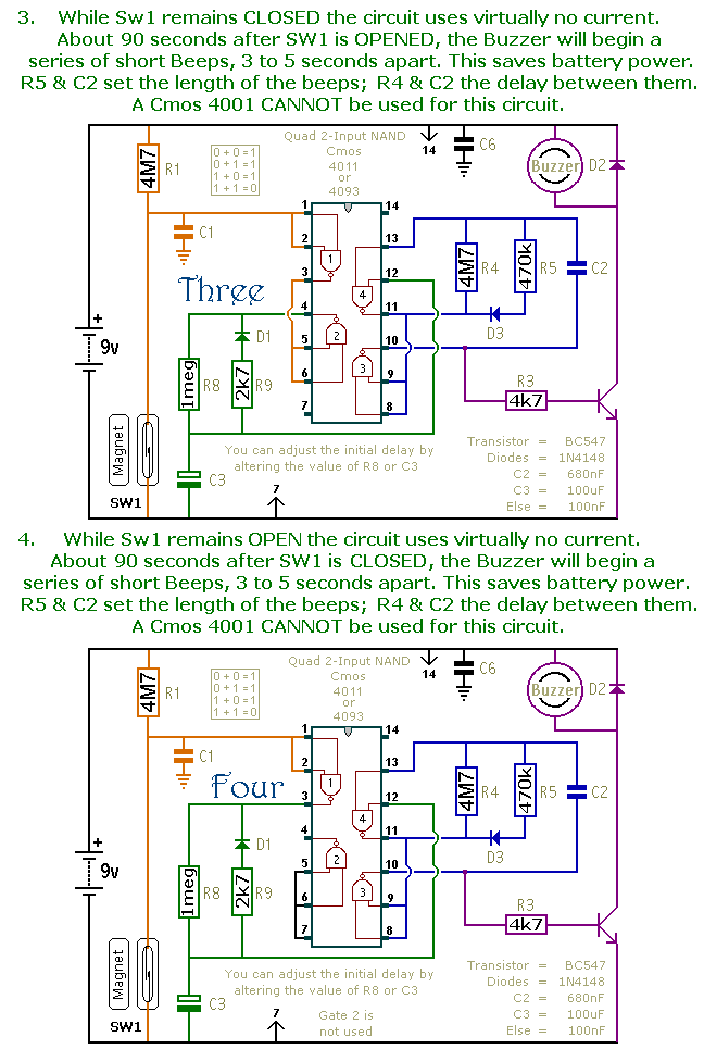
Schematic Diagrams 3 & 4
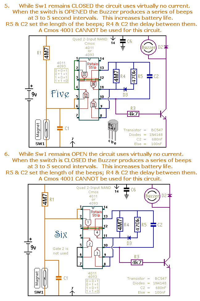
Schematic Diagrams 5 & 6
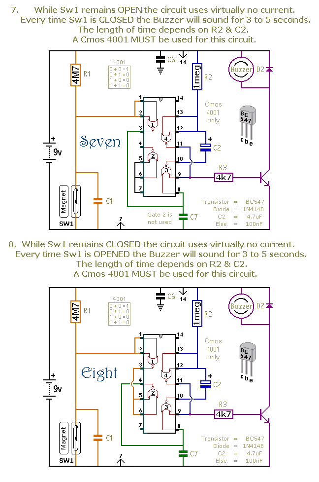
Schematic Diagrams 7 & 8
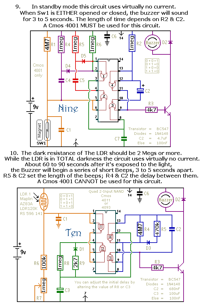
Schematic Diagrams 9 & 10
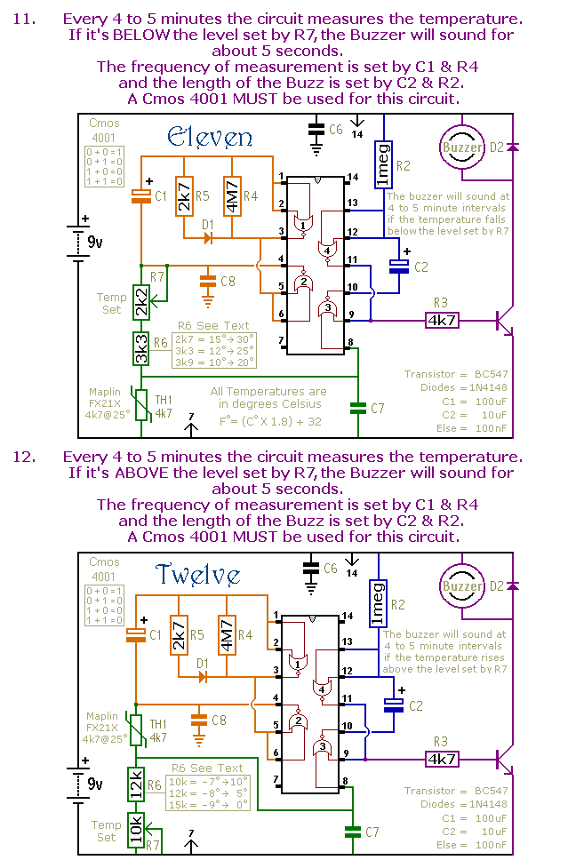
Schematic Diagrams 11 & 12
The Cmos 4093 is the Schmidt-Trigger version of the Cmos 4011. For present purposes the two are interchangeable. However, the 4093 has an improved switching performance. It's most noticeable when the time periods are extended substantially.
The precise length of any time period will depend on the characteristics of the actual components you've used - especially the tolerance of the capacitors - and the exact switching voltages of the Cmos Gates.
In the case of circuits 11 & 12 - treat the values of R6 & R7 as a rough guide. The switching point of Gate 3 and the characteristics of the thermistor will determine the actual temperature range available. Changing the value of R6 will allow you to access different areas of the temperature scale - while changing the value of R7 will allow you to alter the width of adjustment available.