You can use the free
SIMetrix Circuit Simulator to run
My Simulations. Or you can use my observations, tips and techniques - to help you create a suitable file for a different simulator programme. If you do decide to create your own simulation - it may still be worthwhile to download SIMetrix and run my simulations for comparison.
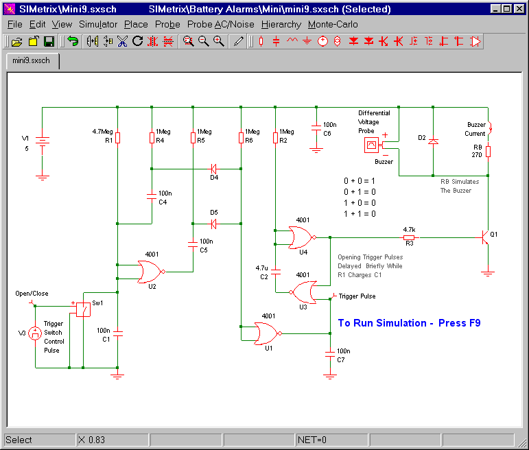
Circuit No.9
This circuit uses a small piezo buzzer. But you can also connect the coil of a small relay to the buzzer terminals. I've used a 270 ohm resistor (RB) to simulate my buzzer and/or relay coil. The differential voltage probe measures the voltage across the resistor. And the state of the buzzer / relay - is determined by the level of that voltage.
Mini-Alarms 9 & 10
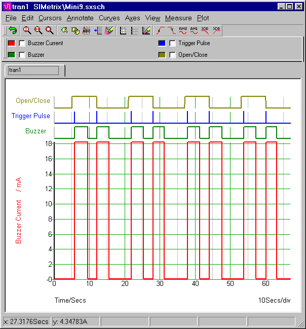
In the graph below - the top line represents Sw1. Five seconds into the simulation - V3 starts to open and close Sw1 - at regular intervals. This produces a series of short trigger pulses - one every time Sw1 opens - and another every time it closes. You'll note that the opening pulses are delayed slightly. This is the time it takes for R1 to charge C1.
Circuit No.9 - Graphs
Mini-Alarms 9 & 10
Each individual pulse triggers the monostable - and sounds the buzzer for about 3 seconds. The length of time the buzzer sounds - is controlled by the values of R2 & C2. The bottom red line represents the current that flows through the 270 ohm resistor. It's roughly 18mA.
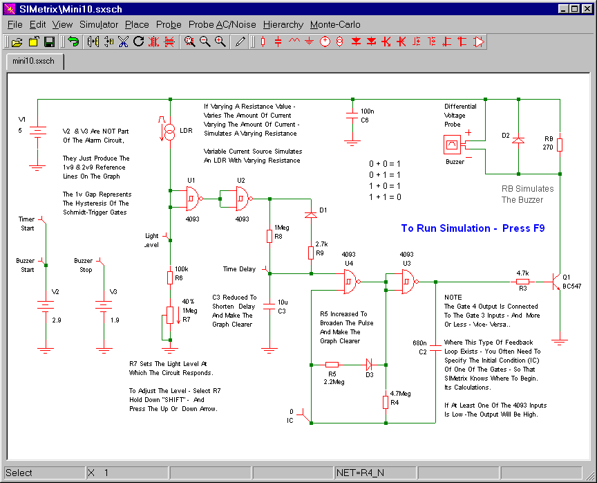
Circuit No.10
This circuit uses a small piezo buzzer. But you can also connect the coil of a small relay to the buzzer terminals. I've used a 270 ohm resistor (RB) to simulate my buzzer and/or relay coil. The differential voltage probe measures the voltage across the resistor. And the state of the buzzer / relay - is determined by the level of that voltage.
Mini-Alarms 9 & 10
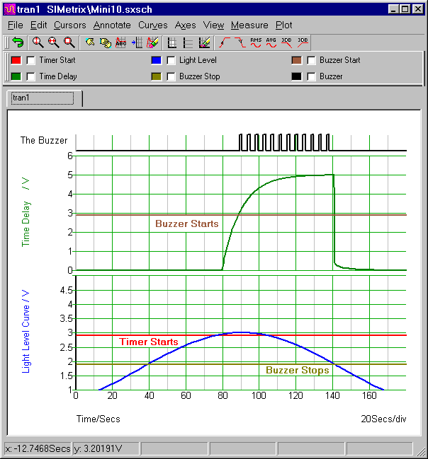
In the graph below - the blue curve represents the light level. Over a period of about 3 minutes - it rises from darkness on the left - to reach full brightness in the middle - and then it returns to darkness on the right. When it crosses the horizontal red line - the time delay starts. And - when the green delay curve crosses the brown line - the buzzer starts.
Circuit No.10 - Graphs
Mini-Alarms 9 & 10
Because of the hysteresis of the Cmos 4093 gates - the buzzer will not stop sounding until the light level falls below the bottom horizontal line. That is - below about 2-volts. At that same time - C3 quickly discharges through R9 & D1. And the delay timer resets.
Adjusting R7 changes the points at which the two horizontal lines - intersect the blue curve. I picked a very bright light level. Increasing the value of R7 - triggers the circuit at lower light levels. Reducing the value of R7 - triggers the circuit at higher light levels. To make your own adjustment - select R7 - hold down the "shift" key - and press either the "up" or the "down" arrow.
Why Are The Simulations 5-Volts?
The Cmos Models that come with SIMetrix 5.40 are designed for a 5-volt supply. And, to keep matters simple, I've set up a 5-volt simulation. However - the alarm itself is designed to work over a range of supply voltages. So included in the
Download Material - you'll also find 9v and 12v simulations. To run these additional simulations successfully - you'll need to install my 9v & 12v Cmos models. This is very easy. Simply drag and drop the "MyMods.lb" file into the small "SIMetrix Command Shell" window. And - when asked - confirm that you want to install the new models. Don't Worry! You're not overwriting anything. All the existing models are still there.


