Free Details Of How To Build A Simple Keypad Circuit With Optional Enhanced Security Features.
Introduction
The prototype of the Parallel Keypad Switch was built using only the Stripboard Layout as a guide. So - if you have faithfully reproduced that layout - you will have a working circuit.
Once you're satisfied that your layout is correct - and you have made a careful and thorough check of the underside of the board - it's time to power-up the circuit and test its operation. This is always an anxious moment. If you construct a lot of circuits - you might consider building the Current Limiting Power Supply - or alternatively - you could add the Simple Current Limiter to your existing PSU. Both will let you set an upper limit on the amount of current supplied to your circuit - and so protect it from any serious damage.
Setup
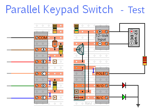
A resistor and a couple of LEDs are all that's needed to demonstrate that the relay contacts are switching properly. And you can simulate the keypad-switches using short lengths of wire.
If You Find a Problem
If - during the test - you find that something is not working properly - a careful inspection of the circuit board should turn up the cause of the problem. Where you've cut the board to size - look for small loose strands of copper left behind by the saw. Check the board for short-circuits caused by component leads touching each other. If an LED is not lighting - check that it's connected the right way round. It can also happen that the stripboard itself is faulty. I have seen cases where the copper tracks have not been completely severed from one another during manufacture.
If you've built your circuit using the specified components - and you've followed the step-by-step construction guide described on the Support Page - chances are that any bug will be caused by something minor - a component connected the wrong way round - a missing or unwanted solder bridge - or an incomplete cut in the track.
If you can't see anything obvious - adopt a systematic approach to faultfinding. Begin by double-checking that all of the cuts in the tracks have been made - that they are all In The Right Place - and that they sever the track completely. Use a magnifying glass - and backlight the board. It only takes the smallest strand of copper to cause a problem.
When you're satisfied that the tracks have been severed in all the right places - check that you have made - and correctly placed - all 5 solder bridges. Check especially the bridge that connects pin 7 - to the track below the IC. Mark each bridge with a felt tip pen - or something similar - so that it can be easily identified later.
Next, carefully examine the full length of each track. If you backlight the board - it makes potential problem areas easier to spot. Look for unwanted solder bridges. Your felt tip markings will tell you which ones should be there - and help you identify any that shouldn't be there.
If all else fails and you still haven't found the cause of the problem - work your way through the assembly instructions on the Support Page. Check each individual component and link - to make sure that it's present and correctly positioned.
Print out the drawings and mark off the components as you go. Pay particular attention to the orientation of the diodes, the transistor and the electrolytic capacitor. Make sure that Pin 1 of the IC is in the top left-hand corner - and that all of its pins are correctly inserted into the socket. Take your time and examine each individual component carefully.
Alternatively - you can take the following approach - suggested for those who have not used the stripboard layout.
If You Have Designed Your Own Layout
For faultfinding purposes you can think of the circuit in two distinct halves. There is the code input section that results in pin 10 going high - and the output section that causes the relay to energize and de-energize.
Try to get the output section working first. Start by disconnecting the end of R6 - that goes to pin 10. Turn-on the power and touch the loose end of R6 to the negative line. When you do so - the relay should energize. And when you disconnect R6 from the negative line - the relay should de-energize.
Once you have your relay operating correctly - you can reconnect R6 - and check to see if the circuit is working properly. If it's not - examine the code entry section.
Turn-on the power and - using a digital voltmeter - make the following checks. If at any stage you do not get the correct readings - investigate.
- Briefly - touch "E" with the "Common" lead to make sure that the circuit has reset.
- Check that pins 1 2 5 & 6 are all low.
- Touch "A" with the "Common" lead - and check that this takes pin 2 high.
- Do the same in turn - with "B C & D" - and check that pins 2 5 & 6 are taken high respectively.
- Next - connect the common wire to both "A & B". Then check that pin 3 is high - and that it takes pin 12 high.
- Now - add "C & D" to the common wire. Then check that pin 4 is high - and that it takes pin 13 high.
- With pins 12 & 13 high - pin 11 should also be high. Check that pin 11 has taken pin 9 high.
- Next - check that pin 8 is high. If pins 8 & 9 are high - pin 10 should be high also.
- If pin 10 is high - the transistor should be switched off. And the relay should be de-energized.
- Disconnect "A B C & D" from the common wire - and from each other.
- Thanks to R5 - and the first four diodes - "A B C & D" should remain high.
- Next - touch the common wire briefly to "E". D5 should take pin 1 low.
- This should cause all four input pins to go low.
- Pin 10 should also go low - and the relay should energize.
- To test the time-lock - monitor the voltage on pin 8. It should start off high.
- Join the common lead to "E" temporarily.
- Over the next few seconds - the voltage on pin 8 should fall to around zero.
- Disconnect the common lead from "E".
- Over the next minute or so - the voltage on pin 8 should rise above 6v - and go on rising to 12v.
If - when you touch A B C & D briefly with the common wire - pin 10 goes high - and remains high - the code entry has been successful. Since you now have both the code input section and the relay output section working - you can test your circuit using the procedure described at the Top of the Page .
 SUGGESTIONS