The circuit uses a small single pole relay - such as the Omron G2E. The coils of these low voltage DC relays behave just like resistors. I've used a 270 ohm resistor (Ry) to simulate my relay coil. The Differential Voltage Probe measures the voltage across the relay coil. And the state of the relay is determined by the level of that voltage.
The simulated timer is set to energize the relay for 3 minutes - at roughly 27 minutes intervals. In the graph below - the bottom line represents the voltage on pin 12 of the IC - the reset pin. The time starts when power is applied - and a low pin 14 charges C2 rapidly - through R9 & D3. When the negative plate of C2 takes pin 12 low - the red line plunges towards zero volts - and the count begins. The top line represents the state of pin 7. As the count proceeds - pin 7 switches the yellow LED on and off.
Graphs
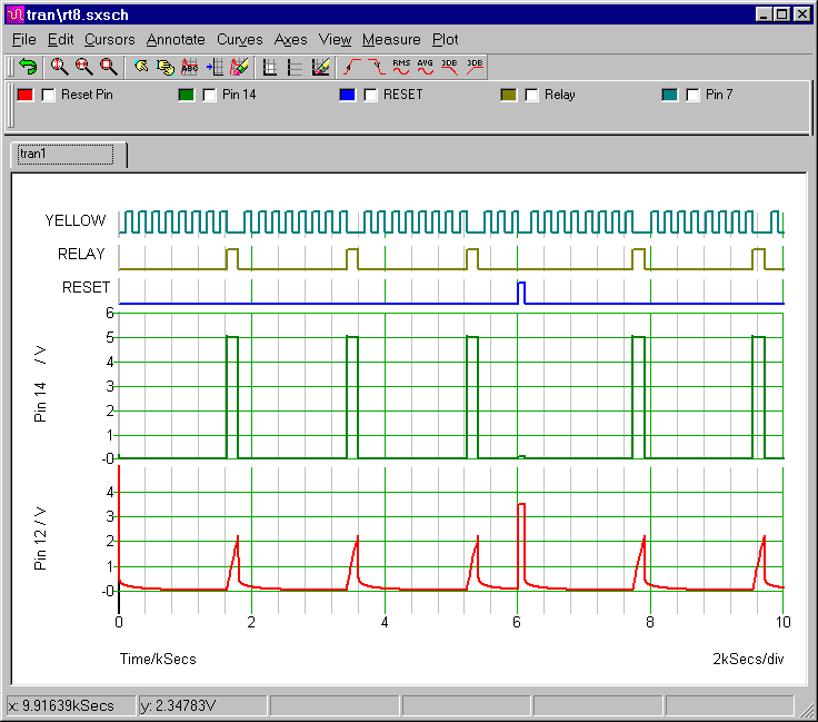
When the yellow LED switches off for the eighth time - pin 14 goes high - the relay energizes - and the count stops. At the same time - the high pin 14 begins to discharge C2 slowly - through R8. As it does so - the (red) voltage on the reset pin rises.
When the voltage on the negative plate of C2 takes pin 12 high - pin 14 goes low - the relay drops out - the count starts again from zero - and the timer sequence repeats. It will go on repeating (27 minutes Off - 3 minutes On) until the power is switched off - or the reset button is pushed.
The blue line represents the reset button. At 100 minutes (6000 seconds) - the button is pushed. This takes pin 12 (the red line) high - and stops the count. When the button is released - pin 12 plunges back towards zero volts. And the (27-minute) Off period - starts again from the beginning
The S1 Control Pulse (V2)
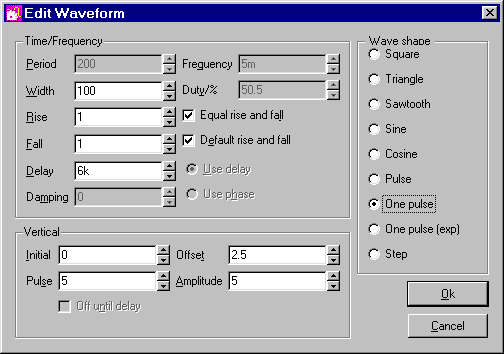
The reset button (S1) is controlled by the waveform generator (V2). After an initial delay of 100 minutes, the generator produces a 5v output pulse. And S1 switches on for the duration of the pulse. The timer's reset is virtually instantaneous. And a much narrower pulse width would have been sufficient. But I choose 100 seconds - so that the pulse could be clearly seen on the graph.
SIMetrix Switches Are Analogue Devices
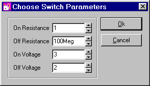
S1 doesn't simply open and close - like a regular push switch. Instead - it has an ON resistance - and an OFF resistance. The default OFF resistance is only 1 Meg. So - even when S1 was off - it was still discharging C2. In order to make S1 behave more like a regular push switch - I had to increase its OFF resistance to something resembling an open circuit. I chose 100Meg.
Analysis Settings
The analysis is straight forward. The "Mode" should be set to "Transient". And the "Stop Time" should be long enough to allow the timer to complete a few cycles. I chose 10 000 seconds - almost 3 hours.
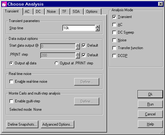
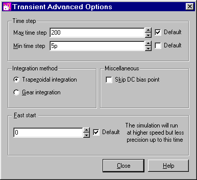
SIMetrix uses your choice of "Stop time" to calculate some of its default settings. Here the stop time figure is relatively high. And one of the resulting default values - the minimum time step - is too high to allow the simulation to run successfully.
You'll find the minimum time step setting - under the "Advanced Options" button. For present purposes - the actual choice of minimum step length is not too important - provided it's short enough. So I chose a really short - five picoseconds.
Where's The Cmos 4060?
The free version of SIMetrix 5.40 has restrictions that prevented me from using the Cmos 4060 model. To get around the restrictions - I had to use the generic 14-bit counter - and a couple of separate inverters. This doesn't have any effect on the accuracy of the simulation. The 4060 is no more than a 14-bit counter - with two inverters. They just happen to be in a single package.
Why Is The Simulation 5-Volts?
The Cmos Models that come with SIMetrix 5.40 are designed for a 5-volt supply. So I've set up a 5-volt simulation. But the circuit itself will work from 5v to 15v. All you have to do is choose a relay - with a coil that will work at the voltage you want to use.