The circuit uses a small single pole relay - such as the 12v Omron G2E. The coils of these low voltage DC relays behave just like resistors. I've used a 270 ohm resistor (Ry) to simulate my relay coil. The Differential Voltage Probe measures the voltage across the relay coil. And the state of the relay is determined by the level of that voltage. A similar probe indicates the state of the LED.
In the graph below - the simulation lasts for a total of 150 seconds. It starts when V2 moves Sw1 to the SET position. That's when the (green) exit delay begins. Thirty seconds later - the door switch opens - the LED lights - and the (blue) entry delay begins.
Just under twenty seconds later - when the blue line reaches 2v5 - the entry delay expires - the relay energizes - and the siren sounds. The alarm sequence ends after 120 seconds - when V2 returns Sw1 to the OFF position. Then - the LED switches off - the relay drops out - and both C2 & C4 discharge rapidly - through D2, D3 & R1.
Graphs
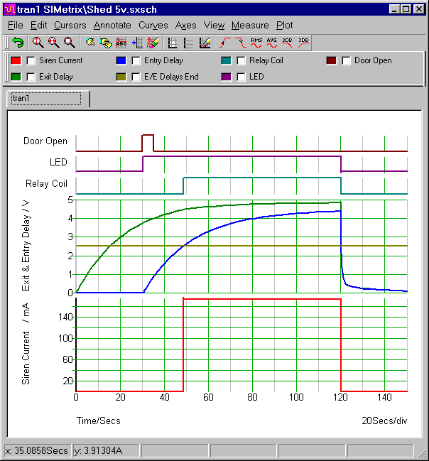
The horizontal 2v5 line represents the switching point of gate 1. When the voltage across C2 rises above that line - the (green) exit delay ends. The same line also represents the gate 3 switching point. When the voltage across C4 rises above that line - the (blue) entry delay ends.
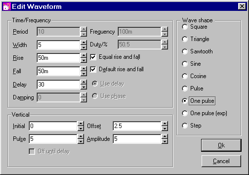
The top line represents the opening and closing of the door. It's produced by V3 & Sw2. Thirty seconds into the simulation - V3 rises sharply to five volts - and Sw2 opens for five seconds. When Sw2 opens - R2 takes pin 2 high - and the alarm activates.
The Trigger Pulse Settings (V3)
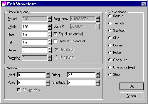
The Alarm Control Pulse (V2)
V2 controls Sw1. It switches the alarm on for two minutes - and then switches it off again. The "Rise" and "Fall" times represent the speed at which the switch operates. That is - the speed at which it changes state. The default values (1% of the "Width" setting) are far too slow. I reduced both to a more realistic one millisecond.
Analysis Settings
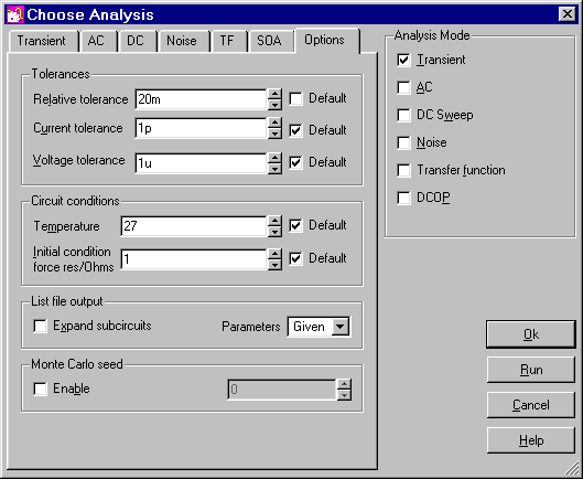
The analysis is fairly straight forward. The "Mode" should be set to "Transient". And the "Stop Time" should be long enough to allow the alarm to complete one "on and off" cycle. I chose 150 seconds.
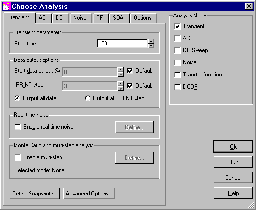
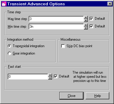
SIMetrix uses your choice of "Stop Time" to calculate some of its "default" settings. If your choice of figure is high - some of the default settings will be too high. And this will prevent the simulation from running successfully.
You could solve the problem by changing some of the individual default settings - such as the minimum time step - or the integration method. But for present purposes - I found that it was sufficient to increase the value of the "relative tolerance". All the other settings can remain at their default levels. You'll find the relative tolerance - under the "options" tab.
Why Is The Simulation 5-Volts?
The Cmos Models that come with SIMetrix 5.40 are designed for a 5-volt supply. So - to keep matters simple - I've set up a 5-volt simulation. However - the alarm itself is designed to work over a range of supply voltages. And included in the
Download Material - you'll find both 9v and 12v simulations.
To run these extra simulations successfully - you'll need to install my 9v and 12v Cmos models. This is very easy to do. Simply drag and drop the "MyMods.lb" file - into the small "SIMetrix Command Shell" window. And - when you're asked - confirm that you want to install the new models. Don't Worry! You're not overwriting anything. All the existing models are still there.