If You Find a Problem
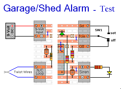
This circuit uses tried and tested components and techniques. When it's assembled as described - it should work first time. If you've designed your own Stripboard / PCB layout - or you're simply trying the circuit out on a breadboard first - check your work carefully.
If you haven't used the specified transistor - make sure that the one you have used is an NPN. And - check its
Pin Configuration. Just because it looks the same as the BC547 - don't assume that its pins are arranged in the same order.
If you haven't used the specified relay - make sure that your relay has the same
Pin Configuration. Just because it looks the same - and fits into the layout - don't assume that its connections are arranged in the same pattern.
If you've built your circuit using the specified components - and you've followed the step-by-step construction guide described on the
Support Page - then the chances are that any bug will be caused by something minor - a component connected the wrong way round - a missing or unwanted solder bridge - an incomplete cut in the track etc. If an LED is not lighting - check that it's the right way round.
If you've cut the board to size - examine the edges where the copper tracks end. Look for loose particles of metal - left hanging by the saw. These particles can short pairs of adjacent tracks together. Remove them with emery paper - or a small file.
Next - double-check that all of the cuts in the tracks have been made - that they're
In The Right Place - and that they sever the tracks completely. Use a magnifying glass - and backlight the board. It only takes the smallest strand of copper to cause a problem.
When you're satisfied that the tracks have been severed in all the right places - check that you have made - and correctly placed - the ten solder bridges. These are just small blobs of solder - used to join pairs of tracks together. Mark each bridge with a felt-tip pen - or something similar - so that it can be easily identified later.
Next - carefully examine the full length of each track. Look for unwanted solder bridges. Your felt-tip marks will tell you which ones should be there - and help you to identify any that shouldn't be there. If you backlight the board during the examination - it makes potential problem areas easier to spot.
If all else fails - and you still haven't found the cause of the problem - work your way through the assembly instructions on the
Support Page. Check each individual component and link - to make sure that it's present and correctly positioned.
Print out the drawings and mark off the components as you go. Take your time and examine each individual component carefully. If you do it right - you'll only have to do it once. Pay particular attention to the orientation of the diodes - the transistor - and the electrolytic capacitors.
Garage / Shed Alarm - Circuit Simulation


