A free circuit diagram for a timer that will simulate a traffic signal sequence.
These are a few examples of sequences that may be produced by the Sequential Timer circuit. I'm not suggesting that they're particularly useful or complex sequences. They're simply intended to illustrate some of the techniques you can use. They will allow you to produce sequences with overlapping and repeating events. They will also allow you fix the total number of times your sequence will repeat - as well as the point in the sequence where the repetition will stop. Please note that I am unable to help any further with the design of specific sequences.
Simple Traffic-Light Sequence
This will simulate a single set of traffic signals. Each green and yellow LED is connected in series with the opposing red LED. Whenever a green or yellow LED is lighting - the opposite red LED will light as well. The on-board resistors are not required. The green and yellow LEDs are connected directly to the four output pins. And the current is controlled by the two 1k resistors - in series with the red LEDs. There's a 5v drop across each pair of series connected LEDs. So the supply needs to be at least 9 volts. See Connecting LEDs In Series
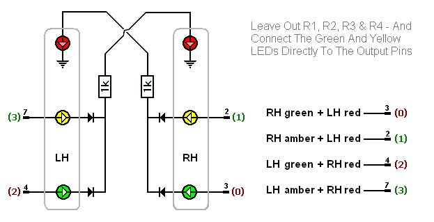
The sequence only has four events. To be more realistic - there would undoubtedly be two further brief periods during which both red LEDs would be lit. This would create a safety buffer between the end of one traffic stream - and the beginning of the conflicting traffic stream. I leave it to you to decide if the slightly improved realism is actually worth the bother.
Multiple Traffic Signals
An IC output pin can only supply enough current for a single pair of traffic signals. But - if we use the pin to operate a transistor switch - we can provide enough current for half a dozen pairs of traffic signals. This circuit has the same output sequence as the previous one. However - here the LEDs take their power directly from the positive line. There are four pairs of series connected LEDs in each set of lights. And the individual pairs of LEDs will light when their transistor switches on.
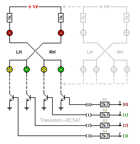
This will control up to six sets of lights. Just connect the green and yellow diodes of each set - to the four transistors. When an output pin goes high - it supplies base current to the transistor. This causes the transistor to switch on - and all the LEDs connected to that transistor will light. With a 12v supply - each set of signals will draw about 8mA. So six sets will draw about 48mA. This is well below the 100mA IC(max) rating of the BC547. If you want more than six sets of lights - simply upgrade to higher spec transistors.
NPN Transistor Switches
This circuit is very similar to the last - only here the transistor switches are used to energize relays and sound a buzzer. I've drawn single-pole relays - but you can use multi-pole relays if they suit your application. The relays can be used to control any type of device - even mains powered. The buzzer might perhaps be included - to indicate that the sequence has terminated.
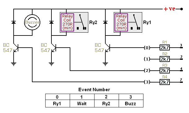
Here - when a pin goes high - it supplies base current to the transistor. This causes the transistor to switch on. The transistor connects the negative side of the relay coil / buzzer to ground. And the relay energizes - or the buzzer sounds. The unused output at pin 2 provides a pause in the sequence - between the time Ry1 de-energizes - and the subsequent energizing of Ry2.
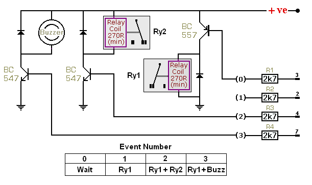
PNP Transistor Switches
This circuit is similar to the previous one - except here the first NPN transistor has been replaced by a PNP transistor. The BC557 reverses the effects of the output pin. While the pin is high - the transistor is switched off. And while the pin is low - the transistor is switched on. When it switches on - the transistor connects the positive side of the relay coil to the positive line - and the relay energizes. Using the PNP transistor turns the first event into a pause. The pause is then followed by three further events - during each of which - Ry1 will remain energized.
Diode Networks
A diode network makes much more complex sequences possible. For example - events in the sequence can be made to overlap - or repeat. The four resistors - R1, R2, R3 & R4 - should be omitted. Instead - the output pins are connected to the transistors - through a network of diodes. The network allows one output pin to control several transistor switches. It also allows one transistor switch to be controlled by several output pins. Below - both relays are energized by pin 2 - and Ry1 is energized by pins 3, 2 & 7. Without the diodes - all four output pins would short together.
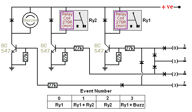
The basic idea is to connect each output pin - to the transistors you want it to control - using a separate diode for each transistor. See pin 2 above. Since one output pin may have to supply base current to many transistors - we need to split the available current into smaller packages. Changing the value of the base resistors to 27k - means that up to ten transistor switches may be connected to a single output pin - and the load on the IC still won't exceed 5mA.
Assuming a 12v supply - each 27k resistor will provide a base current of just under 0.5 mA. The 270 ohm relay coils require a current of 12v ÷ 270 ohms = just under 50mA. So the DC current gain of the transistor switches needs to be roughly 50mA ÷ 0.5mA = 100. This is well within the spec of a typical BC547.
There's one further minor issue to deal with. The diodes create a one-way path. They allow a high output pin to supply current to the base of the transistor - but they prevent a low output pin from connecting the base of the transistor to ground. In other words - the output pin can switch the transistor on - but it can't switch the transistor firmly off.
The additional 27k resistors - connect the base of the transistors to ground. When the high output disappears - these additional resistors turn the transistors firmly off. It's true that the circuit may work without them. But their presence guarantees that the transistors will not continue to conduct - after the output pin goes low.
The value of the additional resistors is not very important. If you make them 10k - or over - they'll work fine. However - resistors are much cheaper when purchased in quantity - even in packs of ten. By limiting the number of different resistor values used in a circuit - you can save money. That's why I specified 27k.
A Finite Number Of Repeats
If you add a second 4017 - you can limit the number of times the sequence will repeat. Pin 13 of the timer is no longer connected to ground. It's connected to one of the IC2 outputs instead. I've chosen output number five. Every time the sequence runs - the clock input of IC2 is taken high - and the count advances by 1. When your chosen output pin goes high - it will "inhibit" the sequential timer. In other words - the sequence will stop repeating.
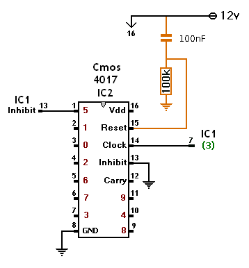
I've shown the clock input of IC2 connected to the last step in the sequence - pin 7. But it can be connected to any of the steps in the sequence. When the required number of repeats is reached - the timer will stop at that step. The step may be a short pause - included in the sequence - for the purpose of stopping the timer with all outputs low.
Increasing The Number Of Repeats
A single 4017 will allow up to 9 repeats. Two 4017s will allow up to 99 repeats - three will allow up to 999 repeats - and so on. In the drawing - I've selected 27 repeats. That is - pin 4 of IC3 - and pin 6 of IC2. While at least one of these two pins is low - it will hold pin 13 of IC1 low - through a diode. And while pin 13 of IC1 is low - the timer will run.
The "Clock" input of IC2 is connected to the last step in the sequence - pin 7. And the "Carry" output of IC2 is connected to the "Clock" input of IC3. When IC1 takes pin 14 of IC2 high - for the 27th time - both of the selected output pins will be high simultaneously. Since pin 13 of IC1 is no longer being held low by one of the pins - it will be taken high by Rx - and the sequence will stop repeating.
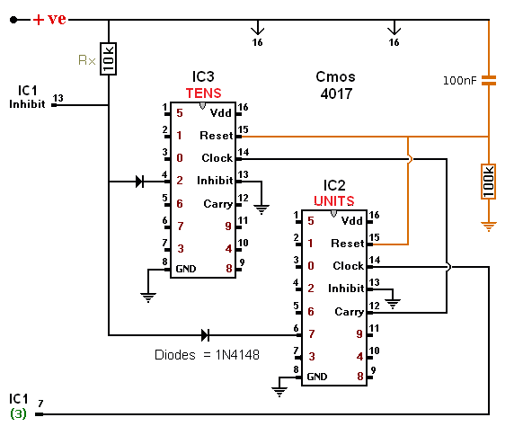
I've shown the clock input of IC2 connected to the last step in the sequence - pin 7. But it can be connected to any of the steps in the sequence. When the required number of repeats is reached - the timer will stop at that step. The step may be a short pause - included in the sequence - for the purpose of stopping the timer with all outputs low.
It's probable that other cmos counters - such as the 4020 - will work as well. A single 4020 will deliver over 16 000 repeats. But your choice of numbers is limited to powers of two - and combinations of powers of two.
 SUGGESTIONS
