A free circuit diagram for a sequential timer with up to 10 separately timed events.
This circuit uses a Cmos 4017 decade counter to create a sequence of four separate events. The number of events in the sequence may be increased to nine or ten. And the length of each event is controlled independently. D13 causes the sequence to repeat continuously. If you leave out D13 - the sequence will run only once. I've used a 12-volt supply in the diagram - but the circuit will work at anything from 5 to 15-volts.
The four outputs are taken from pins 3, 2, 4 & 7 - in that order. The current available from each output pin is controlled by R1, R2, R3 & R4. Each resistor will supply more than enough current to operate a transistor switch. And the switch can be used to energize a relay - sound a buzzer etc.
You're not limited to a series of - "one after the other" - events. You can produce More Complex Sequences - with overlapping and repeating events. You can also fix the total number of times your sequence will repeat - as well as the point in the sequence where the repetition will stop.
Schematic Diagram
Click Here For A Photograph Of The Prototype
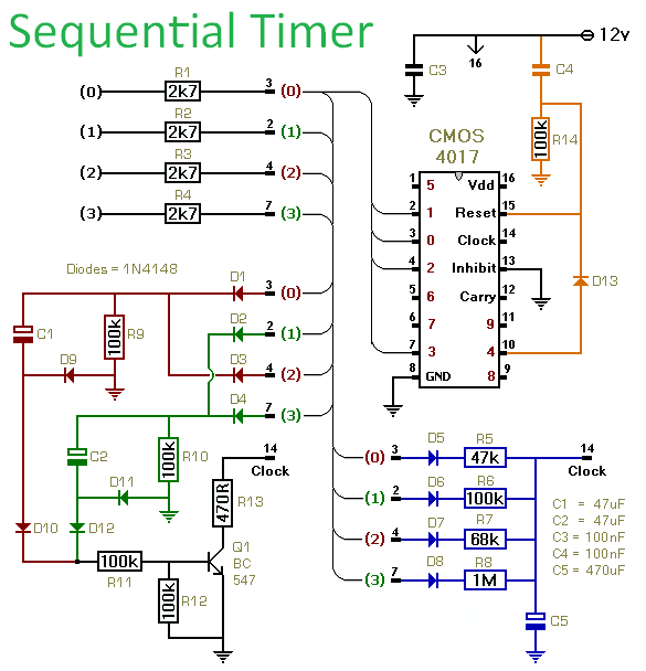
The individual output times are controlled by the value of C5 - and the values of R5, R6, R7 & R8 respectively. At the beginning of each event - Q1 discharges C5. Then the relevant timing resistor takes over - and charges C5 up again. I used a 470uF capacitor in the prototype. And with the resistor values shown in the diagram - the events lasted 38 seconds, 67 seconds, 49 seconds and 9 minutes - respectively. These times each include an initial delay of about 14 seconds - while Q1 discharges C5. Until Q1 switches off - the timing resistors cannot begin to charge C5.
Manufacturing tolerances mean that your results are likely to be different from mine. However - because you're always using the same capacitor to activate the same input pin - the length of each step in your sequence should be fairly predictable. All you need is one reliable practical observation. Then you can calculate the rest.
I got roughly 12 seconds for every 100k/100uF combination. So a 1M resistor and a 100uF capacitor will give about 120 seconds - or two minutes. To this must be added the initial 14 seconds - while Q1 discharges C5. If you want to shorten this discharge time - reduce the value of R11.
There's no theoretical limit on the size of C5. With the 470uF capacitor and the 1M resistor I got just under 9 minutes. So - with a 4700uF capacitor - the 1M resistor should give me just under 90 minutes. And if I increase the resistor to 4M7 - the output should last for around 7 hours.
Veroboard Layout
Click Here For A Photograph Of The Prototype
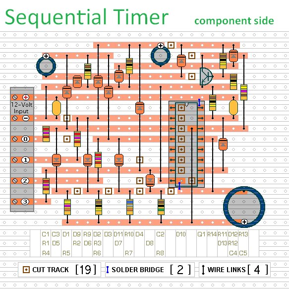
The Support Material for this circuit includes - a step-by-step guide to the construction of the prototype - a detailed circuit description - information on how to change the number of steps in the sequence - and more.
 SUGGESTIONS
