How to build a repeating / non-repeating sequential timer - using a Cmos 4017.
Increasing The Number Of Events
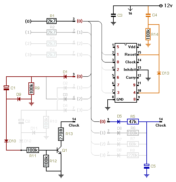
To increase the number of events beyond four - connect the additional outputs as follows:
Each additional output pin requires its own 2k7 current limiting resistor.
Each additional output pin is connected to C5 - through a diode and a timing resistor.
Each additional output pin is connected through a diode to either C1 or C2.
The output pins are connected to the two capacitors alternately.
Output four (pin 10) goes to C1. Output five (pin 1) goes to C2. Output six (pin 5) goes to C1 again - and so on.
If the sequence is to repeat - it must have an even number of events (n).
And output (n+1) should be connected to pin 15 - through D13.
There's one exception to this.
If the sequence has ten events - it will repeat anyway. So there's no need for D13.
If you have an odd number of events - and still want the sequence to repeat - split one of the events in two.
If you don't want the sequence to repeat - it must have nine events or fewer.
And you should leave out D13 altogether.
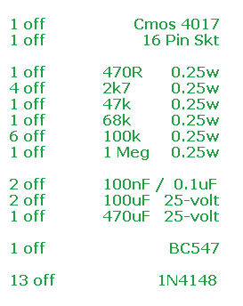
Parts List
|
|
|
|
Construction Guide
Click here if you're new to constructing stripboard projects.
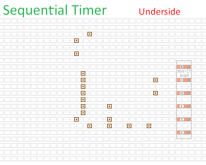
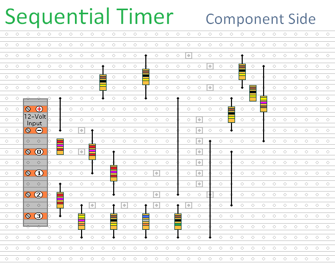
The prototype of this circuit was built using only the Stripboard Layout as a guide. So - if you reproduce the layout - you will have a working circuit. Details of how to Test Your Finished Circuit Board are also provided.
The terminals are a good set of reference points. To fit them - you may need to enlarge the holes slightly. Then turn the board over and use a felt-tip pen to mark the 19 places where the tracks are to be cut. Before you cut the tracks - use the "actual size" drawing to Check That The Pattern is Correctly Marked .
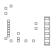
Actual Size Of Pattern
When you're satisfied that the pattern is right - cut the tracks. If you don't have the proper track-cutting tool - then a 6 to 8mm drill-bit will do. Just use the drill-bit as a hand tool - there's no need for a drilling machine. Make sure that the copper strip is cut all the way through. Sometimes a small strand of copper remains at the side of the cut and this will cause malfunction. Use a magnifying glass - and backlight the board. It only takes the smallest strand of copper to cause a problem.
Next fit the Four Wire Links and the fourteen resistors. For the links - I used bare copper wire on the component side of the board. Telephone cable is suitable - the single stranded variety used indoors to wire telephone sockets. Stretching the core slightly will straighten it - and also allow the insulation to slip off.
If you haven't finalized the values of your timing resistors - you could fit veropins in place of R5, R6, R7 & R8. Then you can experiment with different value resistors - until you achieve the time periods you require.
At the bottom of the prototype - I left room to add variable resistors. They would let you set the time periods more accurately. You should still use R5, R6, R7 & R8 to take you close to your target times - then make fine adjustments with the pots.
Next - fit the thirteen diodes. Pay particular attention to their orientation. See the Photograph Of The Prototype. Note that D5, D6, D7 & D8 are facing downwards.
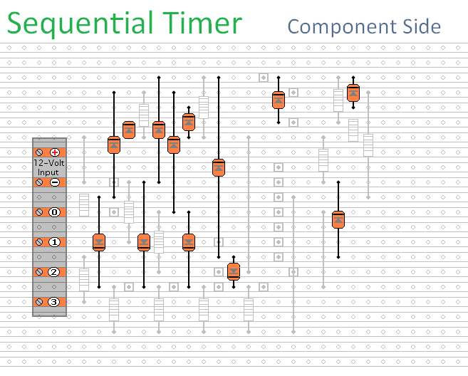
Next - fit the five capacitors - the transistor - and the IC socket. Pay particular attention to the orientation of the electrolytic capacitors. Note that the positive terminal of C5 faces downwards.
Then turn the board over and examine the underside carefully - to make sure that there are no unwanted solder bridges or other connections between the tracks. If you backlight the board during the examination - it makes potential problem areas easier to spot. When you're satisfied that everything is in order - add the 2 solder bridges.
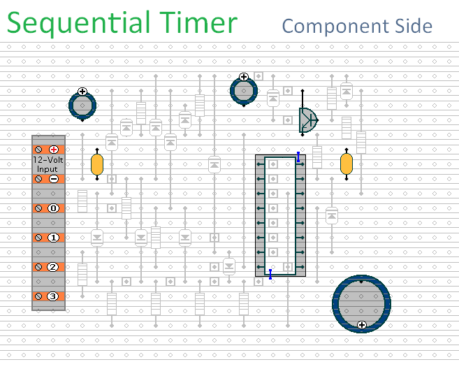
Finish off by inserting the Cmos IC into the socket. Pin 1 of the IC should be in the top left-hand corner. Check that all 16 pins have entered the socket. Sometimes - instead of entering the socket - a pin will curl up under the IC.
You Are Now Ready To Test Your Finished Circuit Board.
 SUGGESTIONS