A simple - low power transformerless PSU.
Mains Electricity Can KILL!
If You Are Not Experienced In Handling Mains Power - You Are Strongly Advised To Leave This Project Alone!
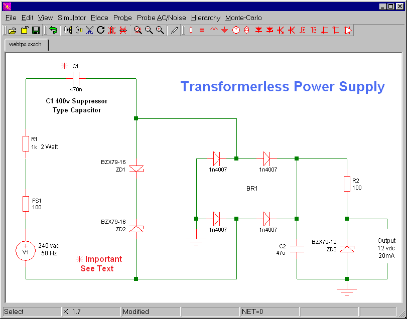
Although Mains equipment can itself consume a lot of current - the circuits we build to control it usually only require a few milliamps. Yet the low voltage power supply is frequently the largest part of the construction and a sizeable portion of the cost. This circuit will supply up to about 20mA at 12 volts.
It uses capacitive reactance instead of resistance - and it doesn't generate very much heat. The circuit draws about 30mA AC. Always use a fuse and/or a fusible resistor to be on the safe side.
There should be more than enough power available for timers - light operated switches - electronic thermostats etc - provided you use an optical isolator as your circuit's output device. (E.g. MOC 3010/3020). If you must use a relay - choose one with a mains voltage coil - and switch the coil with the optical isolator.
 C1 must be a "suppressor" type capacitor. They are made to be connected directly across the incoming Mains Supply. They are high spec components - manufactured to very high standards. And they're generally covered with the logos of several different Safety Standards Authorities.
The low voltage "AC" is supplied by ZD1 and ZD2. You can think of the zeners as the secondary windings a 0,5 VA transformer. Roughly speaking - they produce a 16vac square wave - capable of supplying up to about 30mA.
You can use a single bridge rectifier - or four separate diodes. If you want to - you can replace R2 and ZD3 with a 78 Series regulator. The full sized ones will work but - if space is tight - there are some small 100ma versions available in TO 92 type cases. They look like a BC 547.
You can alter the value of any or all of the zener diodes - to produce a different output voltage. And you can increase the available current by increasing the value of C1. But remember - if you increase the current - you'll also increase the power (Watts) the components have to dissipate.
I'm frequently asked if the circuit can be modified to produce currents of anything up to 50 Amps. IT CAN'T. The circuit is at its best when it's used to provide up to about 20mA DC. If you try to produce any more current - the components start to get very big - and they produce heat. There comes a point when it makes more sense to use a small mains transformer.
The accompanying Support Material includes a detailed circuit description - an explanation of the mathematics - and a number of calculators and simulation files that will help you to explore the effects of changing the component values.

