Transformerless Power Supply - detailed circuit description.
COMMENTS
Homer
SUGGESTIONS

TPS - Support Material
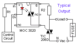
MORE
PSU CIRCUITS

Transformerless Power Supply The Rest of Ron's Circuits Write To Ron More Free-to-Use Circuits Circuit Exchange International


Circuit Description

The aim of the design was to provide a cheap compact power supply for small Cmos circuits. The circuits controlled mains equipment (fans, lights, heaters etc.) through an optically isolated triac - such as the MOC 3020. A current of about 10mA was required to power the diode in the optical isolator. And the Cmos control circuits themselves required far less than that. So a 20mA PSU was more than adequate.

Typical Output

Typical Output Using
an Optical Isolator


We'll begin by looking at the current flowing through the AC section of the circuit. That is - the current flowing through [ FR - R1 - C1 - ZD1 & ZD2 ]. The maximum current flowing through these components is controlled - almost exclusively - by the value of C1. Or - to be slightly more accurate - by the Capacitive Reactance of C1.


Formula for Current in an AC Circuit

Formula for Current 
in an AC Circuit


The resistors in the AC portion of the circuit amount to 1100 ohms in total. This is made up of R1 plus the 100-ohm fusible resistor. R1 limits the peak current through the capacitor. But it has very little effect on the RMS current flowing through the circuit. This is because the contribution R makes to the value of the denominator - is relatively insignificant.

There's no inductance in the circuit. So - 2ΠFL = Zero. Consequently - it makes absolutely no contribution to the value of the denominator. And that only leaves the capacitive reactance of C1.

Formula for
Capacitive 
Reactance

Capacitive reactance - XC - is measured in ohms. Its value depends on both the size of the capacitor - and the frequency of the current. At 50 Hz - the capacitive reactance of a 0.47uF capacitor - is equivalent to a 6k8 resistor. The accompanying Calculator will let you explore the effects of altering the value of the capacitor - and/or the frequency.


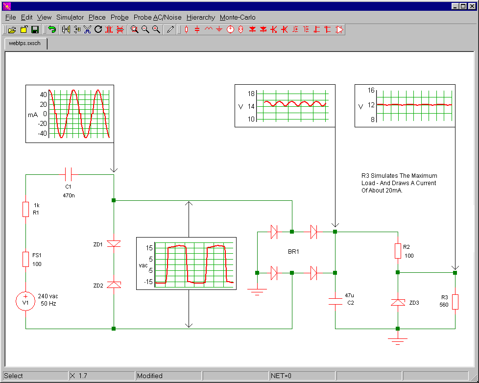
So Why Not Simply Use A 6k8 Resistor?

The power dissipated by the 0.47uF capacitor is lower than the power dissipated by a 6k8 resistor. This is because the current through the capacitor - is always out of phase with the voltage across it.

Watts = Current x Volts

In the case of a resistor - as the voltage across it rises - so also does the current flowing through it. When both the voltage and the current are at maximum - the power reaches its peak.

But the opposite happens with a capacitor. When the voltage across the capacitor is zero - the current through it is at its maximum. At this point the power dissipated by the capacitor is:

Watts = Current x Zero = Zero

Similarly, when the voltage across the capacitor is at its maximum - the capacitor is fully charged. So the current flowing through it is zero. At this point the power dissipated by the capacitor is:

Watts = Zero x Voltage = Zero

It's only somewhere between these two extremes - when both the voltage and the current are below their maximum - that the power reaches its peak. Consequently - this peak has to be lower than that of the resistor.


Calculations

The current flowing through the AC portion of the Transformerless Power Supply is approximately 33mA. It's flowing through ZD1 & ZD2 - and it's available for rectification. You can think of the Zeners as the secondary windings of a mains transformer. However - unlike a transformer - under "no-load" conditions the Zeners will be required to dissipate the whole of the energy available. In other words - if your circuit is to be powered up without R2 & ZD3 or without the output load attached - ZD1 & ZD2 will need to be at least 1-watt.

The AC current 
flowing through the 
16v Zener diodes

The calculator below will allow you to explore the effects of changing the various input values. For example - increasing the frequency causes the current to rise - because the reactance of C1 falls as the frequency rises. Another example - if you reduce the value of the resistor to zero ohms - you'll find that it has very little effect on the output current. The resistor simply limits the peak current. And you'll have to increase it substantially - before it'll cause a serious fall in the output current.


Current In AC Section

 AC Voltage  
Frequency
 Capacitance
 Resistance
AC Current
Mains Voltage - Zener Voltage


The 12vdc Output

There's approximately 33mA flowing through ZD1 & ZD2. And the output from BR1 is about 15vdc. We cannot try to take more than 33mA from BR1 - because it would simply cause a drop in voltage. So we settle for a maximum current of say 30mA. We also want to reduce the 15vdc to 12v - using R2 and ZD3. Since the voltage across ZD3 is fixed at 12 volts - the remaining 3 volts must be across R2. And because we know both the voltage across R2 - and the current flowing through it - we can calculate the value of the resistor using Ohms Law.


How To Calculate 
The Value of R2


The 30 mA flows through ZD3 - and is in theory available to power your circuit. If your circuit only needs about 20mA then the remaining 10 mA continues to flow through ZD3 - so that the voltage drop across R2 remains constant - and the output stays at 12-volts.

If you try to take more than 30mA from the circuit - the voltage drop across R2 will increase beyond 3-volts - and the output will fall below 12volts. In practice - up to 20mA at 12-volts is available.

The Cmos control circuits did not need a particularly smooth supply - and the choice of 47uF for C2 gave a good compromise between physical size and the degree of smoothing. If you have room - and you want more smoothing - then you can use a larger value capacitor. And another electrolytic capacitor - across the output - would give additional smoothing if required.


Circuit Simulator


Below is a drawing of the circuit diagram - taken from the SimMetrix Circuit Simulator. The graphical images were produced separately - by SimMetrix. But - for simplicity - I put them all together in a single drawing. The simulator program is free. And there are versions for both Linux and Windows. If you want to explore this circuit further - you'll find my simulation in this Small Zip File..

Circuit Simulator


C1 MUST be a "suppressor" type capacitor. These are made to be connected directly across the incoming mains supply. They are manufactured to a very high standard - from high spec materials. You can generally recognize suppressor capacitors - because they're covered with the logos of many different Safety Standards Authorities.

The larger the value of C1 - the lower will be its capacitive reactance - and the higher will be the current flowing through it. You can use a single capacitor with a higher value - or you can connect two or more smaller capacitors in parallel. For example - two 0.47uF capacitors connected in parallel will give the equivalent of a 1uF capacitor - and almost double the available current.

However - increasing the value of the capacitor also increases the significance of the contribution R makes to the denominator - R1 has to work harder. And the extra current flowing in the circuit - means that the resistors and Zener diodes will have to dissipate more energy (Watts). If C1 equals 1uF then R1 needs to be 7 watts, and the 16-volt Zeners need to be 2 watts.

This brings us to the circuit's main limitation. It's really at its best when it's used to provide up to about 20mA DC. If you try to produce any more current - the components start to get very big - and they generate more heat. There comes a point when it makes more sense to use a small mains transformer.


Transformerless Power Supply The Rest of Ron's Circuits Write To Ron More Free-to-Use Circuits Circuit Exchange International

Free Web Hosting