All the information you need to build a simple electronic vehicle alarm - using cheap off-the-shelf components.
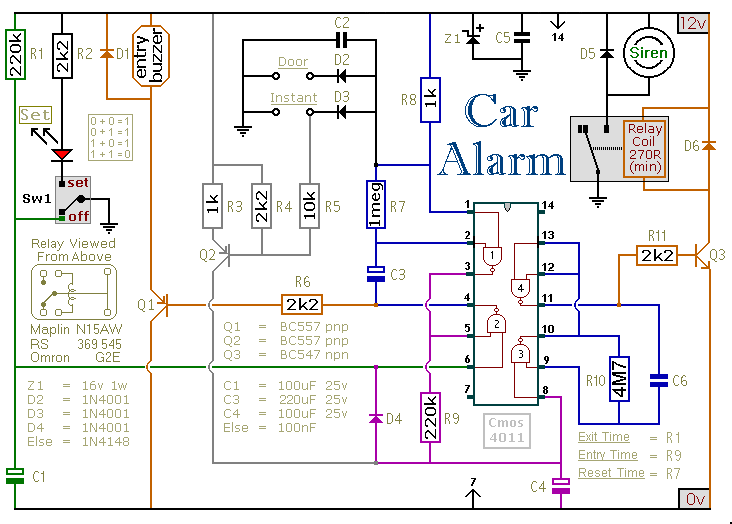
Schematic Diagram
This circuit features automatic exit and entry delays - an optional instant alarm zone - an optional intermittent siren output - and an automatic reset. By adding external relays you can immobilize the vehicle and flash the lights.
The alarm is set by opening Sw1. It can be any small 1-amp single-pole change-over switch - or for added security you could use a key-switch.
For automatic operation - use the contacts of a small relay in place of Sw1. Wire the relay coil so that it's energized while the ignition is on. Then - every time you turn the ignition off - the alarm will set itself.
Click Here For A Photograph Of The Prototype
Once Sw1 is opened you have about 10 to 15 seconds to get out of the vehicle and close the door behind you. When you return and open the door the buzzer will sound. You have 10 to 15 seconds to move Sw1 to the off position. If you fail to do so - the siren will sound.
The output to the siren is intermittent. That is - it switches on and off. The speed at which it switches on and off is set by C6 & R10. If you want a constant siren output - leave out C6 & R10 - and connect pins 8 & 9 of the Cmos 4011 together.
One of the alarm's inputs is connected to the vehicle's existing door-switches. This provides the necessary exit and entry delays. It's usually sufficient to connect a single wire to just one of the door switches. These switches are generally all connected in parallel - with the return through the chassis.
You can add extra normally-open switches to the door-circuit if you wish - but note that any additional switches will have to be able to carry the current required by your vehicle's interior light.
Any number of normally-open switches may be connected - in parallel - to the "Instant" input. Since they don't have to carry the current for the interior light - you can use any type of switch you like.
You may want an instant alarm on the bonnet - the boot - the rear-hatch - the rear-doors etc. It doesn't matter if these already have switches connected to the door-circuit. Simply fit a second switch and connect it to the instant input. It will override the delay circuit. You can use the chassis for the return. However, a ground terminal is provided if - for any reason - you need to run a separate return wire for either zone.
If you're not using the instant zone then leave out D3 and the four components coloured grey in the diagram - that is Q2, R3, R4 & R5.
The exit delay is set by R1 & C1 - the entry delay by R9 & C4 - and the reset time by R7 & C3. The precise length of any time period depends on the characteristics of the actual components used - especially the tolerance of the capacitors and the exact switching points of the Cmos gates. However - for this type of application - really accurate time periods are unnecessary.
While any trigger-switch remains closed - the siren will continue to sound. About 2 to 3 minutes after all of the switches have been opened - the alarm will reset.
The circuit is designed to use an electronic Siren drawing 300 to 400mA. It's not usually a good idea to use the vehicle's own Horn - because it can be easily located and disconnected.
However - if you choose to use the Horn - remember that the alarm relay is too small to carry the necessary current. Connect the coil of a suitably rated relay to the "Siren" output. This can then be used to sound the Horn - flash the lights etc.
The Support Material for this circuit includes a step-by-step guide to the construction of the circuit board, a parts list, a detailed circuit description and more.
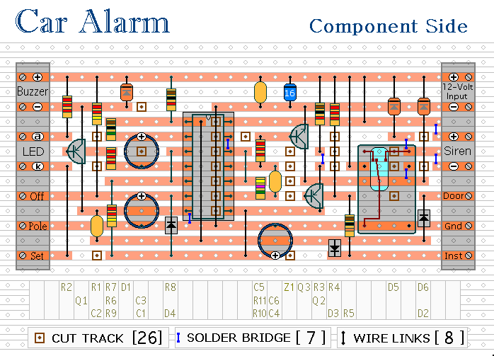
Veroboard Layout
Click Here For A Photograph Of The Prototype
The circuit board and switches must be protected from the elements. Dampness or condensation will cause malfunction. Fit a 1-amp in-line fuse AS CLOSE AS POSSIBLE to your power source. This is VERY IMPORTANT. The fuse is there to protect the wiring - not the alarm. Exactly how the system is fitted will depend on the make of your particular vehicle. Consequently, I CANNOT give any further advice on installation.
Add An Automatic Immobilizer
Before fitting this or any other immobilizer to your vehicle - carefully consider both the safety implications of its possible failure - and the legal consequences of installing a device that could cause an accident. If you decide to proceed - you'll need to use the highest standard of materials and workmanship.
 Remember that the relay MUST be large enough to handle the current required by your ignition system. Choose one specifically designed for automobiles - it will be protected against the elements and will give the best long-term reliability. You don't want it to let you down on a cold wet night - or worse still - in fast moving traffic!!!
Please note that I am UNABLE to help any further with either the choice of a suitable relay - or with advice on its installation.
Remember that the relay MUST be large enough to handle the current required by your ignition system. Choose one specifically designed for automobiles - it will be protected against the elements and will give the best long-term reliability. You don't want it to let you down on a cold wet night - or worse still - in fast moving traffic!!!
Please note that I am UNABLE to help any further with either the choice of a suitable relay - or with advice on its installation.
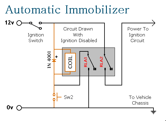
When you turn-off the ignition, the relay will de-energize and the second set of contacts (RLA2) will break the ignition circuit - automatically immobilizing the vehicle.
When the ignition is switched on again the relay will not energize - and the vehicle's ignition circuit will remain broken. You must press Sw2 to energize the relay. It then latches itself on using the first set of contacts (RLA1) - while the second set of contacts (RLA2) completes the connection to the ignition circuit.
The design has a number of advantages. It operates automatically when you turn off the ignition - so there's no need to remember to activate it. The relay uses no current while the ignition is off - so there's no drain on the battery. To de-activate it you'll need to have the ignition key and you'll need to know the whereabouts of the push-switch.
Sw2 only requires a single wire because its return is through the chassis. It carries no load other than the current required by the relay-coil. So almost any small "momentary-action, push-to-make" switch will do. For extra security Sw2 could be key-operated.
Vehicle Alarm - Support Material
 SUGGESTIONS