All the information you need to build a practical vehicle alarm.
A Detailed Circuit Description
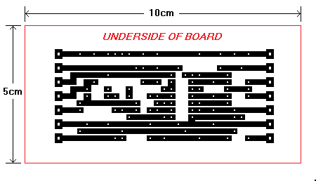
The printed circuit board is based on the original Veroboard Layout. It was drawn with the Paint programme - using a very Simple Technique. The red box is
not the edge of the board. It's just there to help confirm that the printout is the right size. It's designed to be printed at 100 dpi.
I didn't actually make the board myself. I don't have the necessary equipment. I'm obliged to Marcelo - in Buenos Aires. He made the prototype PCB - using the drawing below. I've since produced a Second Version of the layout - where I've replaced the wire links with copper tracks. You may prefer to try that one instead.
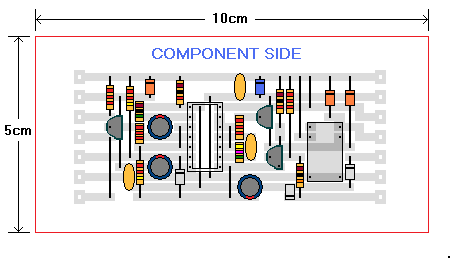
PCB Layout
Actual Size
|
|---|
|
|
Right click on the image. And - from the context menu - select "Save Picture As.." Open your saved picture with Paint - and check the print resolution. Click on "Image" - and then on "Attributes". The resolution should be "100 x 100 dots per inch".
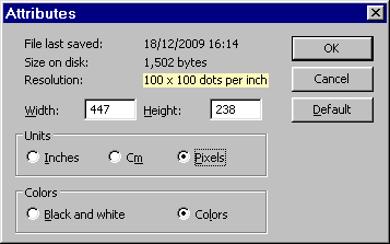
If - for any reason - the print resolution has changed - it can be restored to 100 dpi using one of the techniques described at the bottom of the Stripboard Template page.
 SUGGESTIONS
