Everything you need to know - to build a simple Cmos timer.
Introduction
You can build useful and reliable timer circuits - with a single Cmos inverter. We'll begin by looking at some of the techniques available. And we'll produce a number of simple and useful designs. Then we'll string four of these simple timers together - to create a practical Two-Zone Burglar Alarm.
Although I've divided the material into five separate sections - most of what you need to know is in the first part of the first section. Once you understand how Circuit No.1 works - the rest is easy. The remaining circuits - including the alarm circuit - are just simple variations on Circuit No.1
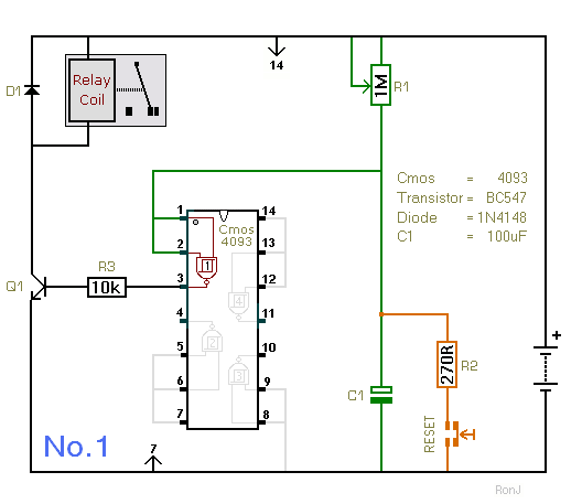
Circuit No.1
The small arrows - top and bottom - indicate that pin 14 is connected to the positive line - and pin 7 is connected to the negative line. I've used a SPCO/SPDT relay in the diagram. But you can use a multi-pole relay - if it suits your application.
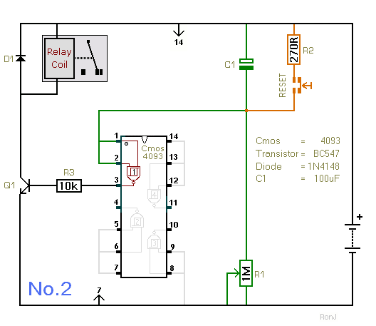
Circuit No.2
The timers will work at anything from 5-volts to 15-volts. All you have to do - is choose a relay with a coil that suits the voltage you want to use. The BC547 will switch 50mA - comfortably. If your relay coil needs more than 50mA - upgrade the transistor to say a BC337.
 SUGGESTIONS